4
B1d.1
4/06
Supercedes 8/05
PACOPACO
PACOPACO
PACO
PUMPS
grooved before the concrete sets to provide a suit-
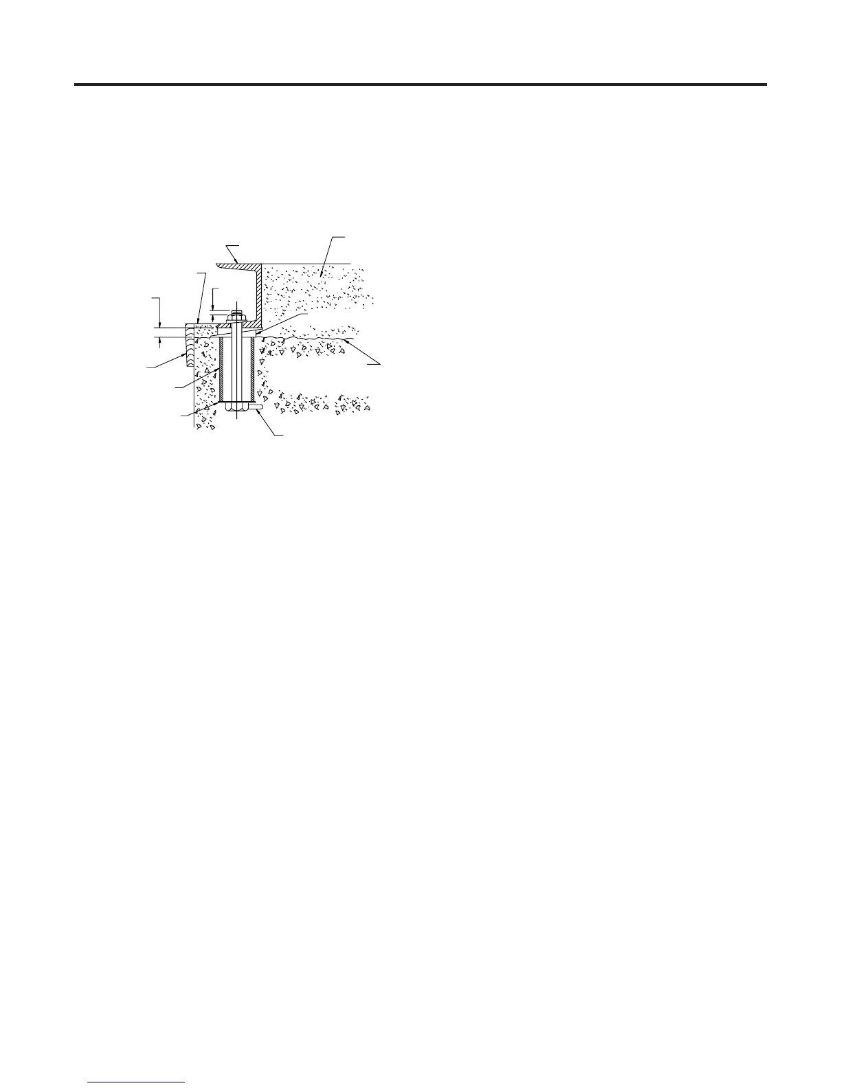
able bonding surface for grout. Anchor bolts should
be set in pipe sleeves for positioning allowance, as
shown in Fig. 2a. Allow enough bolt length for grout,
lower base plate flange, nuts and washers. Allow
the foundation to cure several days before proceed-
ing with pump installation.
F. SECURING THE BASE PLATE
• After the concrete pad has been poured and set,
lower the pump base plate over the anchor bolts and
rest it on loose adjustment wedges or shims placed
G. PIPING-GENERAL
• Do not use pump as a support for piping! Use
pipe hangers or other supports at proper intervals to
provide complete piping support near the pump.
• Both suction and discharge piping should be inde-
pendently supported and properly aligned to insure
no strain is transmitted to the pump when the bolts
are tightened. Use of expansion joints or vibration
pads does not preclude the need to properly support
the piping.
• Do not spring or force piping when making
connections!
• Make sure all piping is as direct as possible.
• Avoid unnecessary bends and fittings.
H. SUCTION (INLET) PIPING
The sizing and installation of suction piping is particu-
larly important. It must be selected and installed in a
manner that minimizes pressure loss and permits suffi-
cient liquid flow into the pump during starting and opera-
tion. Many NPSH problems can be traced directly to
improper design of suction piping systems. Observe the
following precautions when installing piping:
• Suction piping should be as direct as possible, and
ideally the length should be at least ten times the
pipe diameter. Short suction piping can be the same
diameter as the suction opening. Longer piping
should be one or two sizes larger (depending on
length), reducing to the diameter of the suction open-
ing near the pump.
• Use an eccentric reducer, with the eccentric side
down, as shown in (Fig. 3a on page 5) when
reducing pipe diameter to the diameter of the pump
suction opening.
• At no time should suction piping be smaller in
diameter than the pump suction opening.
• Horizontal suction lines should follow an even
gradient, if possible. A gradual upward slope to the
pump is recommended for suction lift conditions,
and a gradual downward slope for positive suction
head.
• Avoid any high points, such as pipe loops, as shown
in (Fig. 4a on page 5), that may create air pockets
and throttle the system or produce erratic
pumping.
24" along each side.
• Shims or wedges must be placed to raise the bottom
of the base 3/4" to 1-1/4" above the pad, allowing
clearance for grout. Level the pump shaft, flanges,
and base plate using a spirit level, adjusting the
wedges or shims, as required.
• Check to make sure the piping can be aligned to the
pump flanges without placing any strain on either
flange.
• After pump alignment has been established, put
nuts on foundation bolts and tighten them just enough
to keep the unit base plate from moving. Construct a
form or dam around the concrete pad and pour grout
in and around the pump base. (See Fig. 2a). Grout
compensates for uneven foundation, distributes the
weight of the unit, and prevents shifting. Use an ap-
proved, non-shrinking grout (such as Embeco 636 by
Master Builders, Cleveland, Ohio or equivalent).
Allow at least 24 hours for this grout to set before
proceeding with piping connections.
• After the grout has thoroughly hardened, check the
foundation bolts and tighten if necessary. Recheck
the pump alignment after the foundation bolts are se-
cured.
BASE PLATE
.75 TO 1.25
ALLOWANCE FOR
GROUT
DAM
PIPE SLEEVE
WASHER
WEDGES OR SHIMS
LEFT IN PLACE
LUG
FINISHED
GROUTING
.25
TOP OF FOUNDATION LEAVE
ROUGH CLEAN & WET DOWN
GROUT
FIGURE 2a: Anchor Bolt Installation.