11
ENGLISH
Electric heater Aqua compact
MA45-25 GB Translation of the original instructions (Swedish)
Drawing no: M10879-3
2017-12-14 ASA
Installation elvärmare Aqua Compact
1.
6.
7.
10.
2.
3.
4.
3.
5.
9.
>
5
0
0
>
2
0
0
8.
>
2
0
0
min 200
Pipe connections are made BEFORE electrical installation.
The electric heater should be installed horizontally according to the drawing, so that it is always fully lled with water.
Under no circumstances may it be started without being completely lled with water.
• Connections must be made using PVC pipe with at least 200 mm of straight length before and after the heater.
The standard version’s connection is glued to PVC pipes with an outside diameter of 50 mm (inside diameter min. 42 mm).
Connection A: glued to PVC pipe with outside diameter Ø1½" (inside diameter min 42 mm).
Connection B: hose with an inside diameter min. 35 mm is connected and must be clamped to ensure 200 mm straight length
before and after the heater.
• Do not install the shut-o valve between the heater and the pool. If a valve is required here, it must be a non-return valve.
• The heater must not be covered, placed close to combustible material or in direct sunlight.
• If the heater is placed against combustible material, a reproof board or the like must be placed between the heater and
combustible material. The board must cover 10 cm outside the heater's outer dimensions.
• The heater must not be installed in a position that is exposed to the elements and must be protected against the ingress of
water.
• If the position of the heater is such that there is a risk of freezing, the installation must be carried out in such a way that the
heater can be drained of all water.
Failure to follow the installation instructions invalidates the product warranty.
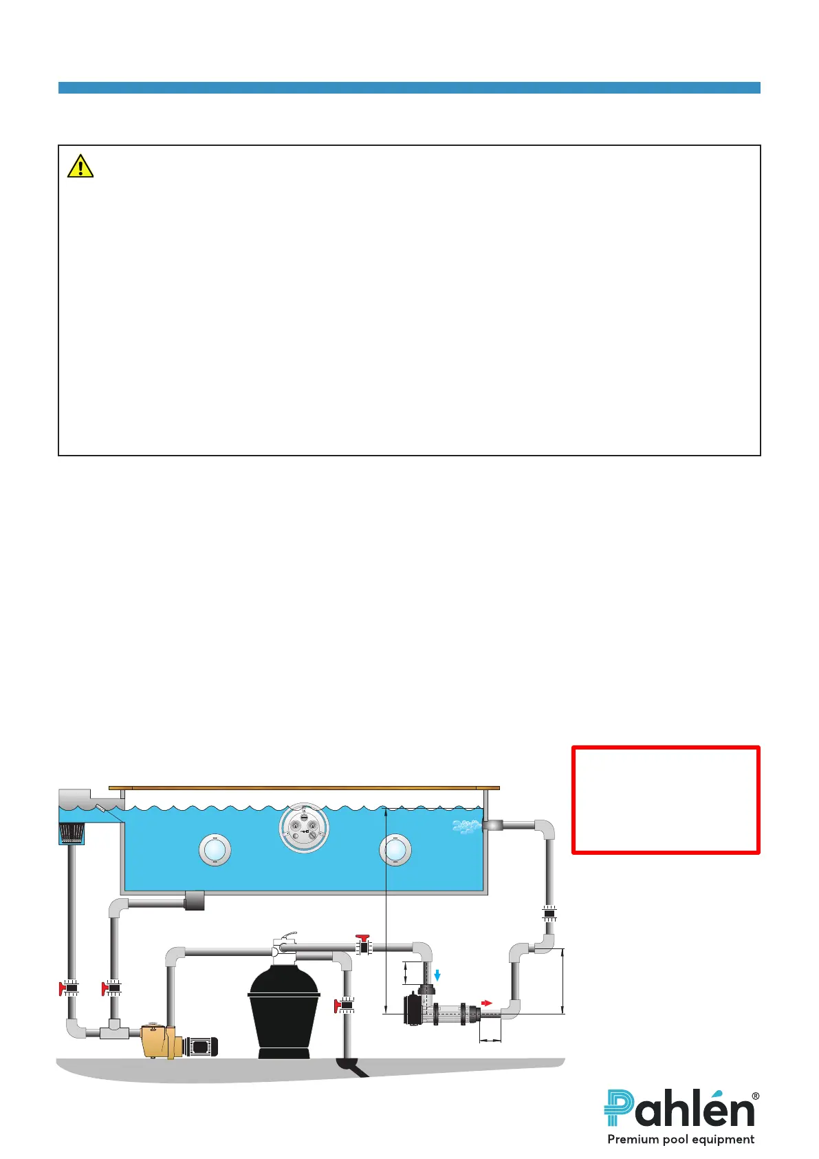
Installation example pipe
1. Skimmer
2. Inlet
3. Light
4. JetSwim
5. Main drain
6. Pump
7. Filter
8. Electric heater
9. Check valve
10. Drain
NOTE!
The electric heater must
always be located at least
200 mm below the water
surface.
WARNING
• The water inlet on this appliance must not be connected to the inlet water from any other
heating system.
• This appliance must ALWAYS be installed at least 200 mm below the normal water level,
see the installation example.
• Valves must not be installed so that the ow of water through the heater can be unintentio-
nally turned o.
• The installation must be carried out in such a way that the heater cannot be self-drained in
the absence of pool water circulation and air pockets cannot be formed.
• The heater must be installed on the return line to the pool AFTER a possible lter.
• If necessary, chlorine, acid or similar should be dosed after the heater in the direction of ow
.
• The ow direction marking on the heater indicates the connections that apply for the inlet
and outlet.
Installation in circulation systems