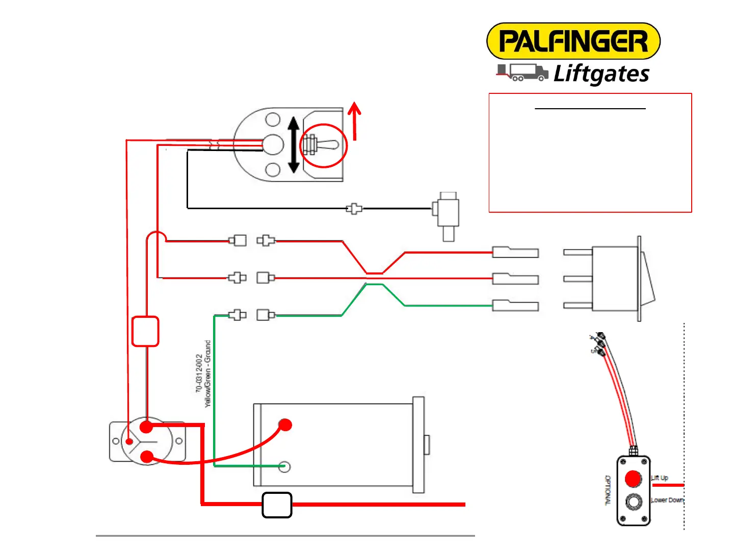
PLR Electric Schematic RAISE/LIFT Function
#6 Black Wire Lower/Down
#4 Black Wire
Power
To Toggle Switch
POWER
LOAD
GROUND
Blue Wire Load
To Toggle Switch
Green/Yellow Wire To
Ground Stud On Motor
#5 Black Wire Power
Raise To Starter
Solenoid
One (1) Lowering
Solenoid On
Cylinder
150A
CIRCUIT BREAKER
2 GA CABLE FROM BATTERY
2 GA CABLE FROM BATTERY
Ground Stud
Power Stud
Brown Wire Power
From In-Line Fuse
15A
ATC
FUSE
Red Line = Active Power
Green Line = Ground
(Green/Yellow Wire)
Black Line = Inactive Power
OPTIONAL
HAND HELD
REMOTE
2 Button Control
UP - Solenoid - 5 - RED
DOWN - Release valves - 6 -
YELLOW
12V HOT - On-off switch - 4 -
GREEN
RAISE/LIFT FUNCTION
Toggle switch or hand held remote
activated in RAISE/LIFT position.
Starter Solenoid and Motor energized.
Hydraulic fluid is pumped through
valve into cylinders raising platform.
19