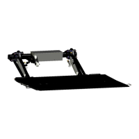
Do you have a question about the Palfinger ILP and is the answer not in the manual?
Defines key measurement terms like Bed Height, Mount Tube Setting, and Ground Clearance.
Provides critical notes for liftgate mounting, including ground clearance and bed height.
Details installation dimensions for 800mm arm ILP with a square tube main frame.
Details modifications for mount plates to accommodate short overhangs.
Illustrates bed height ranges and cut-out information for 800mm arm on square tube frames.
Details installation dimensions for 800mm arm ILP with a round tube main frame.
Illustrates bed height ranges and cut-out information for 800mm arm on round tube frames.
Details installation dimensions for 900mm arm ILP with various platform sizes.
Illustrates bed height ranges and cut-out information for 900mm arm.
Guides on installing bed extensions and dock bumpers onto the truck chassis.
Details the critical steps for installing the main liftgate frame.
Step-by-step guide for installing the gate structure using liftarm pins.
Instructions for attaching and securing the liftgate platform.
Explains how to adjust the torsion springs for proper gate operation.
Covers connecting the main power supply from the battery to the liftgate unit.
Details the installation and connection of the circuit breaker for system protection.
Specific instructions for switch installation with roll-up door equipped vehicles.
Specific instructions for switch installation with swing door equipped vehicles.
Instructions for installing the main ON/OFF or cab cut-off switch.
Guide for installing an optional remote hand control for the liftgate.
Diagram and explanation of the main power supply wiring for the liftgate.
Provides the overall electrical wiring schematic for the liftgate system.
Displays the hydraulic circuit diagram for the 2-cylinder lift gate system.
Details the correct placement and inspection of all safety and operational decals.
| Brand | Palfinger |
|---|---|
| Model | ILP |
| Category | Lifting Systems |
| Language | English |


 Loading...