7
Electrical Installation
Revision 1.3 - 23 -
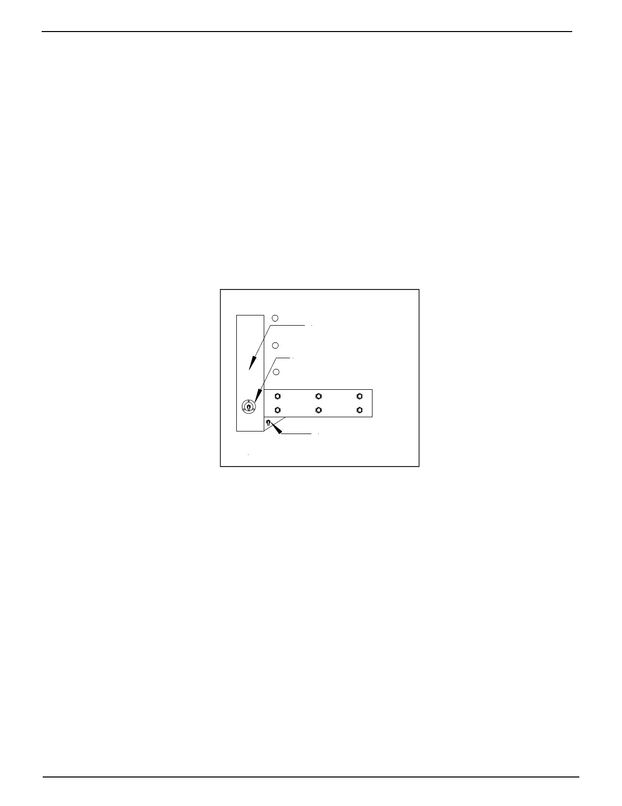
7.3.2 Swing Door setup
Locate Area under bed extension or under body that will not be obstructed by doors when open
1. Drill 7/8” hole for control wire
2. Disconnect the three (3) connectors from up/down control wire
3. Route wire through rear post and back to pump/motor box
4. Attach switch using 2ea. #8x1-1/2” self tapping screws
5. Reconnect cables as connections removed.
6. Verify wire is clear of all moving parts, such as platform etc. and securely tied up.
7. Check that up function operates with switch in up position on your installation.
Swap #1 & #2 wires in pump/motor box to correct if necessary.
8. Heat shrink connections
Swing Door/Optional
Up/Down Switch Location
(Cup Mount Sold Separately)
Typical Trailer
On/Off Installation
Corner Post
Swing Door
Figure 23 Swing Door switch installation