7
Electrical Installation
Revision 1.3 - 22 -
7.3 UP/DOWN Switch Installation
Determine location for fixed toggle switch on corner post in a way that
the operator can view the platform and surrounding areas while
operating the liftgate.
7.3.1 Roll up door setup
Locate area on rear post of body where switch can be reached by operator from ground and body floor.
- Approximately 24” up from floor
1. Drill 7/8” hole for control wire
2. Disconnect the three (3) connectors from up/down control wire (Mark cable function)
3. Route wire through rear post and back to pump/motor box
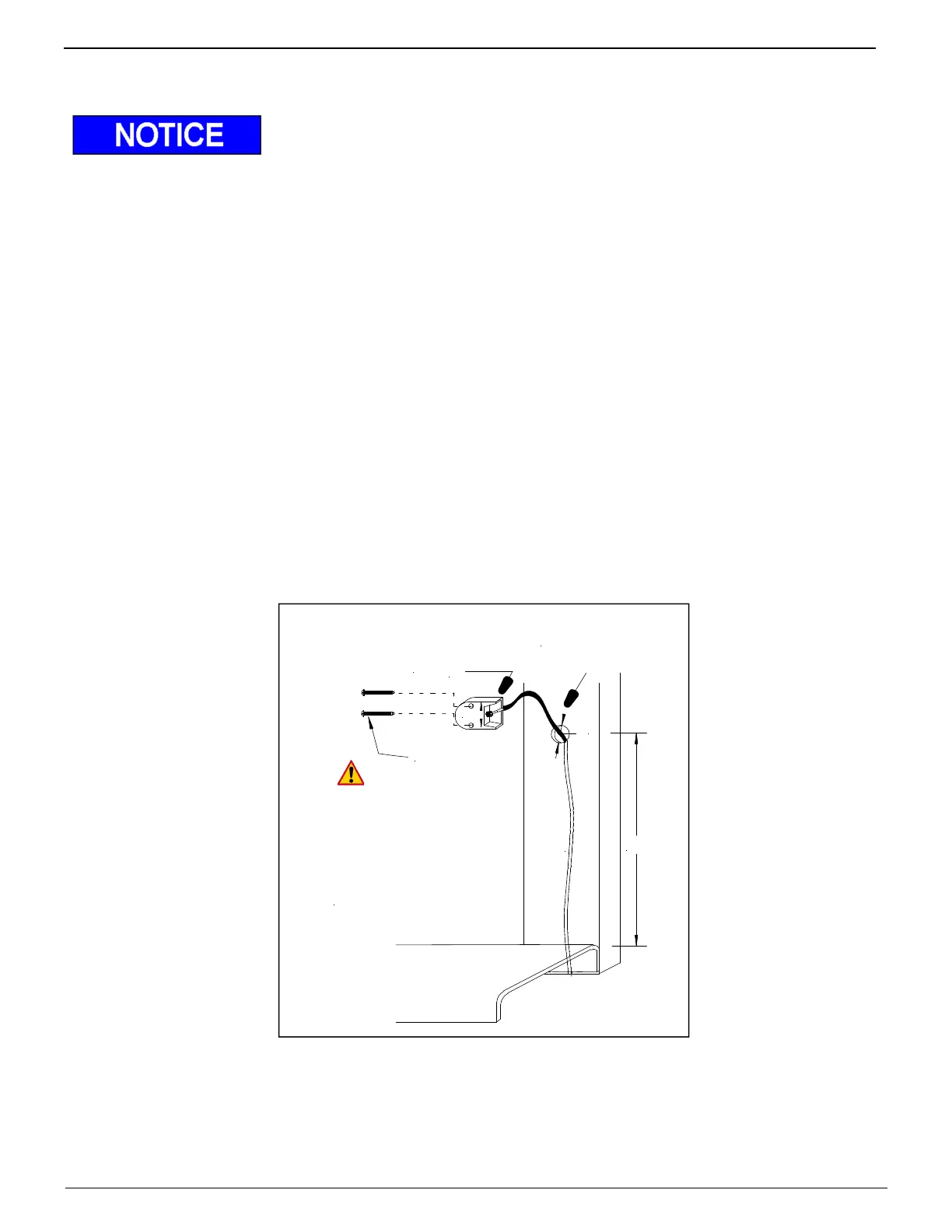
4. Attach switch using 2ea. #8x1-1/2” self tapping screws (Figure 22)
5. Reconnect cables as connections removed.
6. Verify wire is clear of all moving parts, such as platform etc. and securely tied up.
7. Check that up function operates with switch in up position on your installation.
Swap #1 & #2 wires in pump/motor box to correct if necessary.
8. Heat shrink connections
Rear Vertical
Body Post
Switch
# 8 x 1-1/2"
Pan Head
MB B
DO NOT use impact,
power drill or power driver
to torque screws tight
SCREWS MUST BE
HAND TIGHTENED
ø 7/8"
24"
approx.
Figure 22 Roll up door switch installation