Lubrication and Final Inspection
Revision 1.3 - 28 -
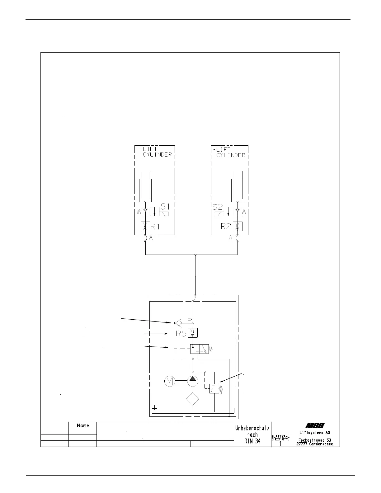
8.1 Hydraulic Schematic and Decal Placement
Functions:
Lift: M
Lower: S1+S2
Pressure Relief
2850 PSI
200 bar
Restrictor Valve R5
Flow Divider
Functions:
S1 and S2 = Release Valve for lowering function
R1 and R2 = Flow Restrictor located inside hose adaptor on lift cylinder
R5 = Restrictor Valve located in power pack
Flow Divider is not activated, when fluid is going back into the power pack
Access for
pressure gauge
Datum
01.08.08
Hydraulic Schematic
HACKBARTH
2 cylinder lift gate
Figure 29 Hydraulic schematic