12 Operating Your AT2KD
1-800-773-7931 WWW.PALSTAR.COM
Before Operating
1. To avoid possible damage to the AT2KD set TUNE, IN-
DUCTOR, and POWER RANGE switches as outlined in
the chart before applying transmitter power.
2. Begin tuning with your transmitter/amp into the tuner set
at a low output power setting (50-100 Watts).
Tuning
1. Select the band and frequency of desired operation.
2. Set TUNE and INDUCTOR controls to the suggested
setting before applying transmitter power (see chart). Ac-
WARNING: DO NOT OPERATE THE AT2KD
WITH THE COVER OFF.
TUNE INDUCTOR
SUGGESTED ACTUAL SUGGESTED ACTUAL
160 M 50-52 56(SW IN)
80 M
50-52 136
60 M
50-52 177
40 M
50-52 201
20 M
50-52 232
17 M
50-52 236
15 M
50-52 236
12 M
50-52 236
10 M
50-52 236 MAX 249
BAND
Note: The AT2KD must be supplied with 12VDC to
operate the relay in order to use it on the160 Meter
band.
1-800-773-7931 WWW.PALSTAR.COM
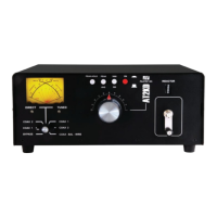
Front Panel Description 9
the back panel must be supplied with 12 VDC for this to
function.
6. INDUCTOR 18 µH continuously variable ceramic roller
inductor driven by a crank handle coupled to a gear-
driven precision mechanical counter.
7. 160 METER SWITCH Pushing this button to the IN po-
sition switches in extra inductance for the 160 Meter
Band. The button should be in the OUT position for use
on all other bands — 80 through 6 Meters.
8. TUNE Continuously adjustable differential capacitor.
9. DIRECT/TUNED MODE SWITCH Six-position rotary
switch selects intended RF output coaxial connector and
direct mode (which bypasses the tuning network) and
tuned position (which routes RF through the tuning net-
work).
a. DIRECT BYPASS selects BYPASS COAX connec-
tor, bypassing the impedance matching circuit but pro-
viding SWR, FORWARD and REFLECTED meter read-
ings.
b. DIRECT COAX 1 selects COAX 1 connector, by-
passing the impedance matching network but providing
SWR, FORWARD and REFLECTED meter readings.
c. DIRECT COAX 2 selects COAX 2 connector, bypass-
ing the impedance matching network but providing
SWR, FORWARD and REFLECTED meter readings.
d. TUNED COAX 1 selects COAX 1 connector through
the impedance matching T network.
e. TUNED COAX 2 selects COAX 2 connector through
the impedance matching T network.
f. COAX-BAL-WIRE selects the COAX-BAL-WIRE
output connector and routes RF through the impedance
matching T network.