Do you have a question about the Panasonic AG-CX10P and is the answer not in the manual?
Key safety notices, component importance, and general precautions.
Procedure for resistance check between plug and metallic parts for shock hazards.
Procedure for voltage measurement to check leakage current.
Techniques to prevent static electricity damage to sensitive components.
Guidelines for recycling lithium-ion batteries.
Warnings on recording copyright, rain, moisture, and accessory usage.
Details on mains plug, fuse replacement, and wiring code.
Step-by-step guide for removing and replacing the lithium battery.
Explains the purpose of the service manual for technical information.
Information on lead-free solder and repair precautions.
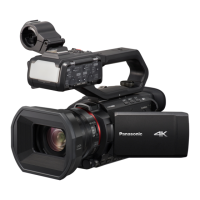
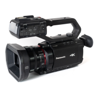
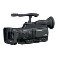
How to identify model suffixes by referring to unit labels.
Power, operating environment, mass, and external dimensions.
Pickup device, pixels, lens, filter diameter, object distance.
Recording media, system frequency, file format, and recording format.
Video compression format and recording audio signal.
Video compression, resolution, frame rate, bit rate, protocols.
Compliance standards, frequency range, encryption, access method.
Specifications for SDI OUT and HDMI terminals.
Built-in microphone and MIC terminal specifications.
Specifications for REMOTE, USB, and DC IN 12V terminals.
Details for LCD monitor and viewfinder.
Specifications for USB interface, LAN, mass, and dimensions.
Power source, output, operating temp, mass, dimensions.
Voltage, capacity, charging current, mass, and dimensions.
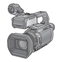
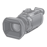
Describes lens hood, lens cover, focus ring, rear ring, ND filter, focus button.
Explains card slots, access lamps, speaker, slot select, user buttons.
Describes display button, diopter, eyepiece, power, WB, AE level, auto/manu.
Details gain, iris, menu buttons, exit, multidial, fan, wireless LAN.
Describes MIC terminal, remote, USB, tripod holes, lens cover, lens, fan outlet.
Explains status indicator, battery release/mounting, viewfinder, REC, HDMI, headphones.
Details DC IN 12V terminal and SDI OUT terminal.
Describes LCD monitor, built-in mic, and accessory shoe.
Explains zoom lever, handle unit mounting, and USER5 button.
Describes handle, mic holder, buckle, clamp, and input terminals.
Explains input switches, channel select, and audio level dials.
Describes channel switches, audio dials, mounting screw, light controls.
Explains hold lever, REC button, mounting hole, and zoom lever.
Steps to enter the service mode menu.
Lists the available functions within the service mode.
Steps to select and change model or destination settings.
Explains the purpose and behavior of model/destination settings.
Steps to access and view usage time, error codes, version.
Details the types of information displayed in the usage time section.
Steps to access and view power-on self-check results.
Explains communication test results displayed by self-check.
Steps to reset operating times for various camera functions.
Lists the operating times that can be reset.
Steps to enter the service adjustment mode.
Outlines the scope of adjustment functions and refers to other sections.
Steps to restore adjustment data from an SD card.
Explains the purpose of restoring adjustment data.
Steps to perform touch panel calibration.
Explains the purpose of touch panel calibration.
Information on required jigs, tools, and inspection methods.
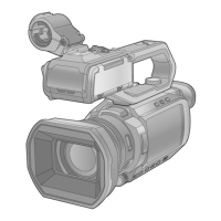
Introduction to the disassembly flow chart for the camera unit.
Visual representation of the disassembly steps for the camera unit.
Diagrams showing the location of Printed Circuit Boards (PCBs) within the camera.
Detailed list of components and steps for disassembling the camera unit.
Safety and handling precautions for disassembly and assembly.
Procedure for removing the lens hood unit.
Procedure for removing the left side case unit.
Procedure for removing the jack PCB.
Procedure for removing the rear case unit.
Procedure for removing the fan duct unit.
Procedure for removing the Wi-Fi SS PCB.
Procedure for removing the DC motor unit.
Procedure for removing the right side case unit.
Procedure for removing the top case unit.
Procedure for removing MF unit and lens frame.
Procedure for removing the EVF case unit.
Procedure for removing SD frame and SD PCB.
Procedure for removing the main PCB.
Procedure for removing the SDI holder unit.
Procedure for removing the main frame.
Procedure for removing the battery case unit.
Procedure for removing the MF unit.
Procedure for removing the camera lens unit.
Procedure for removing the LCD relay PCB.
Procedure for removing the MIC PCB unit.
Procedure for removing the top inner case unit.
Procedure for removing top frame unit and top OP PCB.
Procedure for removing the zoom unit.
Procedure for removing R frame front, menu OP PCB, LCD unit.
Procedure for removing menu OP button and Kurupon unit.
Procedure for removing R frame rear and side R OP PCB.
Procedure for removing R OP button, shutter button, levers, door, panel.
Procedure for removing R OP earth plate and speaker.
Procedure for removing the LCD hinge unit.
Procedure for removing the LCD plate unit.
Procedure for removing the grip belt.
Procedure for removing the 2nd stepping motor.
Procedure for removing the 3rd stepping motor.
Procedure for removing the 4th stepping motor.
Flow chart illustrating the disassembly process for the handle unit.
Diagrams showing the location of PCBs within the handle unit.
Detailed list of components and steps for disassembling the handle unit.
Safety and handling precautions for handle unit disassembly/assembly.
Procedure for removing the left side case of the handle unit.
Procedure for removing the HA XLR PCB unit.
Procedure for removing the top case of the handle unit.
Procedure for removing HA Zoom PCB and Handle LED OP PCB.
Procedure for removing HA LED PCB, light lens, and light cover.
Procedure for removing the right side case of the handle unit.
Procedure for removing USB cover, HA connector PCB, and bottom cover.
Procedure for removing tripod mount and handle grip.
Procedure for removing handle frame piece unit and HA main PCB.
Information on necessary jigs, connection, and adjustment figures.
Lists part numbers for required jigs and tools.
Enumerates specific service fixtures and tools.
Lists recommended measuring instruments for service.
Overview of adjustment items and their applicability to parts.
Steps to initiate the service adjustment function.
Lists the sequence of adjustments performed.
Details on accessing the top screen for adjustments.
Procedure for setting the model during adjustment.
Procedure for naming and saving backup files during adjustment.
Steps for backing up adjustment data to an SD card.
Procedure for checking the status of various switches.
Detailed steps for checking switches on the camera body.
Detailed steps for checking switches on the handle unit.
Procedure for checking switches on both body and handle.
Procedure for calibrating the zoom lever.
Procedure for adjusting camera settings like Iris, Gyro, OIS.
Procedure for performing tracking adjustment.
Procedure for white balance adjustment in indoor lighting.
Procedure for white balance adjustment in outdoor lighting.
Procedure for adjusting ND WB GAIN.
Procedure for adjusting vignetting.
Procedure for performing level adjustment.
Procedure for adjusting reference frequency.
Final screen indicating completion of adjustments.
Steps to activate factory settings.
Details what settings are refreshed by factory settings.
Instructions for setting switches and levers after factory reset.
Comprehensive block diagram of main system components and interconnections.
Diagram showing how various units and PCBs are interconnected.
Exploded view showing assembly of frame parts with reference numbers.
Exploded view illustrating handle unit components with reference numbers.
Exploded view illustrating packing components and accessories.
List of replacement parts for casing components with part numbers.
Continuation of replacement parts list for casing components.
Detailed list of screws used in casing assembly.
Continuation of the screw list for casing components.
List of replacement parts for the handle unit with part numbers.
Detailed list of screws used in handle unit assembly.
List of replacement parts for packing cases, cables, adaptors, manuals.