Do you have a question about the Panasonic AKHCU200 and is the answer not in the manual?
How to change the displayed information on the picture monitor using the ROP.
Order of priority for displays on the picture monitor when events occur.
Details the types of information shown on the picture monitor, including warnings and statuses.
Procedure for showing and closing the unit's menu screens using the MENU button.
Step-by-step guide to navigating and selecting menu items using the SELECT dial.
The initial screen displayed when the MENU button is held down, offering main menu selections.
Accesses settings related to the unit's operational functions.
Contains primary configuration settings for the unit's output signals and modes.
Provides advanced settings for video output, color bars, and signal processing.
Used for adjusting horizontal and vertical sync phase for HD and SD signals.
Allows setting and customizing identification strings displayed on color bars.
Configures intercom audio levels and settings.
Configures unit startup behavior for camera and viewfinder power.
Sets the video level for the analog composite signal output.
Allows setting custom names for ND filters displayed in status.
Configures IP address, subnet mask, and gateway settings for network connection.
Displays software and hardware version information for the unit.
Controls which items (IRIS, status) are displayed on the picture monitor.
Configures display of operational status for various unit functions.
Initializes menu settings to factory defaults and manages system data.
Manages saving/upgrading unit software and settings using a memory card.
Instructions on navigating menus within the web interface.
Process for changing and applying settings using the web interface.
Configuration settings accessible and adjustable through the web browser interface.
Advanced settings for video output and signal processing via the web interface.
Adjusting sync phases for HD/SD signals using the web interface.
Setting BAR IDs on color bars through the web interface.
Configuring intercom audio via the web interface.
Accessing system maintenance functions through the web interface.
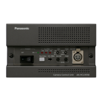
Details pin assignments and signal flow for communication connectors.
Pin assignments for microphone output connectors.
Pin assignments for the MSU connector (future function expansion).
Pin assignments for camera interface connections.
Pin assignments for the intercom connector.
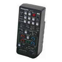
Pin assignments for the Remote Operation Panel (ROP) connector.
| Type | Control Unit |
|---|---|
| Model | AK-HCU200 |
| Manufacturer | Panasonic |
| LAN | Yes |
| Weight | 3.5 kg |
| Video Input | HD-SDI |
| Video Output | HD-SDI |
| Audio Input | 2 x XLR |
| Audio Output | 2 x XLR |
| Network Interface | 10/100/1000BASE-T |
| Control Protocol | RS-422 |
| Power Supply | AC 100-240V, 50/60Hz |
| Video Format | 1080i |
| SD-SDI Output | Yes |
| Operating Temperature | 0°C to 40°C |
| Storage Temperature | -20°C to 60°C |