EasyManua.ls Logo

Panasonic AW-RP150 User Manual

Panasonic AW-RP150
6 pages
To Next Page IconTo Next Page
Page #1 background imageLoading...
Page #1 background image
This document is described functions of AW-RP150 SYSTEM VERSION Ver 2.00-00-0.09. Please
see also the operating instructions of ROPs.
No.3 A ROP setting menu is added so that the selected camera at the AW-RP150
can be activated on the connected ROP.
-
AK-HRP1000/AK-HRP1005 ver.4.80-00-0.03 or higher
- To use the ROP linkage function, PORT number of RP150 has to be same as one of R O P.
Setting ROP
MENU】>AW CONTROLLER LINK
Set up the PORT No. for RP150 to RECEIVE PORTand execute INFO UPLOAD.
Set AW CONT LINK to ON.
Setting RP150
MENU SYSTEM ROP LINK
Set up ROP IPand PORTfor ROP. And execute UPLOAD.
Assign CAMSEL for RP150 and ROP CAMf o r R O P.
Target CAM No. can be set at “ROP CAM” against CAMSEL in RP150.
Initial setting : CAM1 CAM99 is 1 99
CAM100 - CAM200 is NON
In case of no assigned CAMERA, please set it “NON.
When “AW LINK” is turned on, RP150 starts to communicate to ROP.
Operating guide for AW-RP150 Ver2
Question and Answer IconNeed help?

Do you have a question about the Panasonic AW-RP150 and is the answer not in the manual?

Panasonic AW-RP150 Specifications

General IconGeneral
BrandPanasonic
ModelAW-RP150
CategoryDigital Camera
LanguageEnglish

Summary

ROP Setting Menu for Camera Activation

Setting ROP Linkage

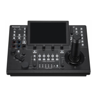
Configure PORT number for RP150 RECEIVE PORT and execute INFO UPLOAD. Set AW CONT LINK to ON.

Setting RP150 for ROP Linkage

Configure ROP IP and PORT, execute UPLOAD. Assign CAMSEL for RP150 and ROP CAM for ROP.

AV-HS6000 Linkage and Switching

SW Link Setting Options

Configure SW IP, PORT, BUSCONT, BUS assignments, and FOCUS ASSIST for AV-HS6000 linkage.

Status Display Settings

Configure TALLY IP, CAM INF, and CAM NAME display settings for camera information.

SW Link Assignment Configuration

TMEM All Delete Function

Executing TMEM All Delete

Delete all TMEM (Tracing Memory) data on the target camera via the MODE menu.

Camera Group Number Status Display

Status Display Enhancements

Indicator for 'Camera Group number' is added under the Status display.

ND Filter Assignment to Knobs

Configuring ND Filter via A.KNOB

Assign 'ND Filter' as an item for A.KNOB1-4, selectable by rotating the dial.

I.Zoom Functionality

I.Zoom Status in Camera Info

View and control 'I.Zoom' status in Camera Info; assignable to User Button.

Assigning I.Zoom to User Buttons

Assign the 'I.Zoom' function to User buttons (USER1-10) for quick access.

CAMSEL OP Menu

CAMSEL OP Operation Mode

Set CAMSEL OP to 'MULTI' to select cameras during operation (PAN/TILT/ZOOM).

IRIS LIMIT Function

Activating Iris Limit

Turn Iris Limit ON for the close direction when Iris position is decided.

PRESET LIST NAME Edit Function

Editing Preset List Names

Edit PMEM names (PMEM1-PMEM100) using F1 for character entry and F2 for deletion.

Preset Button Color Assignment

Assigning Colors to Presets

Assign one of 7 colors to each PRESET button; save settings to SD Card.

PAN/TILT Lever Operation Direction

Setting Control Mode

Set CTRLMODE to 'CAMSEL' for individual camera settings or 'ALL' for same settings on all cameras.

PRESET LIST Display

Preset Information on Status Screen

PRESET LIST is displayed on Status screen, showing PRESET and Lens information.

Related product manuals