Do you have a question about the Panasonic CQ-C5405U and is the answer not in the manual?
Explains identification and handling of lead-free solder PCBs and its properties.
Provides safety precautions for laser diode usage, handling, and operation.
Details proper fuse replacement procedures to prevent damage or fire.
Advises on routine exterior cleaning using dry, soft cloth, avoiding solvents.
Contains specific notes regarding AM/FM block alignment and servo circuit.
Lists technical specifications including power, audio, radio, and impedance details.
Provides physical dimensions and weight of the unit.
Details the function of each pin for the main IC and its connections.
Describes the pins and functions related to the display IC.
Details pins and functions for the CD servo control IC.
Illustrates the internal block diagram of the main IC, showing functional modules.
Shows the primary block diagram for audio signal processing and system control.
Details the interconnection of display, connectors, and system control blocks.
Illustrates the block diagram for the CD servo control system.
Provides the detailed schematic for the main block of the CQ-C5405U model.
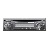
Provides the detailed schematic for the main block of the CQ-C5305U model.
Presents the schematic diagram for the display circuitry.
Shows the schematic diagram for the CD servo control system.
Details the schematic for the connector block and its interconnections.
Shows the component layout for the main/connector PCB from the top.
Shows the component layout for the main/connector PCB from the bottom.
Illustrates the component layout for the display PCB.
Shows the component layout for the CD servo PCB from the top.
Shows the component layout for the CD servo PCB from the bottom.
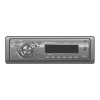
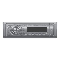
Provides an exploded view of the CQ-C5405U unit for part identification.
Lists all replacement parts for the CQ-C5405U model with part numbers.
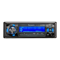
Provides an exploded view of the CQ-C5305U unit for part identification.
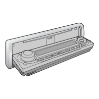
Details the exploded view of the CD deck mechanism for part identification.
Lists replacement parts specifically for the CD player functionality.
Lists items included in the product's packing for shipping and sale.
Presents the left-side schematic for the CQ-C5405U main block.
Presents the right-side schematic for the CQ-C5405U main block.
Presents the left-side schematic for the CQ-C5305U main block.
Presents the right-side schematic for the CQ-C5305U main block.
Shows the left-side schematic for the display block.
Shows the right-side schematic for the display block.
Presents the left-side schematic for the CD servo block.
Presents the right-side schematic for the CD servo block.
| Brand | Panasonic |
|---|---|
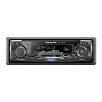
| Model | CQ-C5405U |
| Category | Car Receiver |
| Language | English |