EasyManua.ls Logo

Panasonic CQ-JA1920L

Panasonic CQ-JA1920L
37 pages
To Next Page IconTo Next Page
Loading...
General
Power Supply DC 12V (11V - 16V),
Test Voltage 13.2V
Negative Ground
Current Consumption Less than 4.0A
Power Output 12W×12W
Speaker Impedance 4
AM Radio
Frequency Range 531 - 1,6020kHz
Signal to Noise Ratio 23dB(µV) (S/N 20dB)
FM Stereo Radio
Frequency Range 87.5 - 108.0MHz
Usable Sensitivity 5dB/µV (S/N 30dB)
CD Player
Signal to Noise Ratio More than 90dB
Channel Separation More than 80dB
© 2001 Matsushita Communication Industrial Co.,
Ltd. All rights reserved. Unauthorized copying and
distribution is a violation of law.
AUDI
CQ-JA1920L
CQ-JA1924L
AM/FM MPX ELECTRONIC TUNING
RADIO with Stereo Cassette Tape
Player and CD Player
AUDI No. (CQ-JA1920L) : 8D0 035 195E
AUDI No. (CQ-JA1924L) : 8Z0 035 196
VEHICLE (CQ-JA1920L) : Audi A4
VEHICLE (CQ-JA1924L) : Audi A2
DESTINATION : Europe
SALE DATE : May., 2000
Total Harmonic Distortion Less than 0.02%
Tape Player
Reproduction System 4-Track, 2-Program Stereo
Tape Speed 1-7/8” (4.76cm/sec)
Signal to Noise Ratio More than 42dB
Wow and Flutter 0.09% (WRMS)
Stereo Separation More than 30dB
Dimensions** 178×164.5×110mm
* Specifications and the design are subject to possible modification
without notice due to improvements.
** Dimensions and Weight shown are approximate.
Doldy noise reduction manufactured under license from Dolby
Laboratories Licensing Corporation.
“Dolby” and the double-D symbol
are trade marks of Dolby
Laboratories Licensing Corporation.
AUTOMOTIVE ELECTRONICS
Specification
ORDER No. AED0101023
Question and Answer IconNeed help?

Do you have a question about the Panasonic CQ-JA1920L and is the answer not in the manual?

Panasonic CQ-JA1920L Specifications

General IconGeneral
ModelCQ-JA1920L
CD PlaybackYes
MP3 PlaybackYes
USB InputYes
Auxiliary InputYes
BluetoothNo
DisplayLCD
Remote ControlNo
Tuner BandsAM/FM
Channels4

Summary

Specification

General Specifications

General power, current, and output specifications.

Radio Specifications

AM/FM radio frequency range, sensitivity, and signal-to-noise ratio.

CD Player Specifications

CD player signal-to-noise ratio and channel separation.

Tape Player Specifications

Tape player reproduction system, speed, and signal-to-noise ratio.

Unit Dimensions

Physical dimensions of the unit.

Features

Laser Product Safety Information

Warning and safety precautions for laser product operation.

Rear View and Connectors

Rear Connector Pin Assignments

Detailed pin descriptions for rear panel connectors C, D, A, and B.

Front View and Functions

Front Panel Controls and Indicators

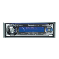
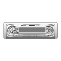
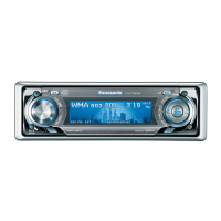
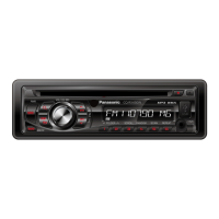
Description of front panel controls, buttons, and LCD display elements.

Alignment Instructions

Alignment Conditions and Dolby NR Procedures

Conditions required for alignment and specific Dolby NR alignment steps.

Alignment Points

Visual Alignment Location Diagram

Diagram showing physical points for alignment adjustments.

Wiring Connection Diagram

System Wiring Interconnections

Diagram illustrating the interconnection of main blocks and components.

Block Diagrams

Main Block Diagram

Schematic showing the main functional blocks and their interconnections.

CD Servo Block Diagram

Schematic detailing the CD servo control system's functional blocks.

Terminals Description

Main Block Terminal Details

Detailed description of pins and functions for the main block connector.

DSP Block Terminal Details

Detailed description of pins and functions for the DSP block connector.

Display Block Terminal Details

Detailed description of pins and functions for the Display block connector.

CD Servo Block Terminal Details

Detailed description of pins and functions for the CD servo block connector.

Package and IC Block Diagrams

Main Block IC Diagram

Block diagram illustrating ICs within the main block and their connections.

CD Servo Block IC Diagram

Block diagram illustrating ICs within the CD servo block and their connections.

Replacement Parts List

Main, Amp, DSP, Connector Parts

List of replacement parts for the main, amplifier, DSP, and connector blocks.

Mechanical Parts List

List of mechanical components and their part numbers for replacement.

Exploded View - Unit

Unit Assembly Breakdown

Visual breakdown of the unit's assembly with numbered parts.

CD Player Parts

CD Servo Block Parts

List of parts specific to the CD servo block.

Exploded View - CD Deck

CD Deck Assembly Breakdown

Visual breakdown of the CD deck mechanism with numbered parts.

Tape Player Parts

Tape Player Components List

Comprehensive list of tape player parts including diodes, capacitors, resistors, connectors, electrical, and mechanical components.

Exploded View - Tape Deck

Tape Deck Assembly Breakdown

Visual breakdown of the tape deck mechanism with numbered parts.

Schematic Diagram - 1

Tape Block Schematic

Circuit diagram detailing the tape block's electrical connections and components.

Schematic Diagram - 2

Display Block Schematic

Circuit diagram detailing the display block's electrical connections and components.

Main-2 Connector Block Schematic

Circuit diagram for the second main block and connector interfaces.

DSP Block Schematic

Circuit diagram detailing the DSP block's electrical connections and components.

Amp Block Schematic

Circuit diagram detailing the amplifier block's electrical connections and components.

Related product manuals