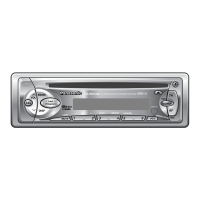
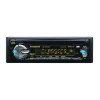
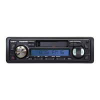
9.1. Main Block
IC600 : C2CBHF000217
Pin
No.
Port Descriptions I/O
(V)
FM
(V)
AM
(V)
CD
(V)
1 NC (Connecting to ground) - 0 0 0
2 NC (Connecting to ground) - 0 0 0
3 NC (Connecting to ground) - 0 0 0
4 AVSS Analog ground - 0 0 0
5 AF MUTE AF mute O 5.1 5.1 5.2
6 AMP-CNT Power Amp. stand-by O 5.1 5.1 5.2
7 AVREF Reference voltage - 5.1 5.1 5.2
8 CD-MISO CD data I 0 0 0
9 CD-MOSI CD data O 0 0 2.4
10 CD-SCK CD clock O 0 0 5.1
11 CD.C DATA CD.CH data I 0 0 0
12 NC No connection - - - -
13 CD.C CLK CD.CH data shift clock I 0 0 0
14 REM OUT CD.CH remote cont. O 5.0 5.0 5.0
15 BZOUT Beep output O 0 0 0
16 PLL-MISO Data from PLL I 5.1 5.1 5.1
17 PLL-MOSI Data for PLL O 0 0 0
18 PLL-CLK Clock for PLL O 5.1 5.1 5.2
19 PLL-CE PLL chip enable O 0 0 0
20 NC No connection - - - -
21 NC No connection - - - -
22 NC No connection - - - -
23 NC No connection - - - -
24 CD-STB CD strobe O 0 0 5.1
25 CD-A0 CD address 0 O 0 0 4.4
26 CD-RST CD reset O 0 0 5.1
27 CD-RFOK CD RFOK signal I 0 0 5.0
28 CD-LOCK CD lock signal I 0 0 5.0
29 CD-LIMIT CD limit sw I 0 0 5.1
30 CD-SW2 CD SW2 I 5.1 5.1 0
31 NC No connection - - - -
32 NC No connection - - - -
33 Vss Ground - 0 0 0
34 S.LED Not used - - - -
35 ST-IND FM stereo detection I 5.0 5.1 5.1
36 IC2-CLK Electronic volume clock O 5.1 5.1 5.2
37 IC2-DATA Electronic volume data I/O 5.1 0 5.2
38 NC No connection - - - -
39 NC No connection - - - -
40 NC No connection - - - -
41 LCD-MOSI LCD data output O 0 0 0
42 LCD-MISO LCD data input I 5.0 5.0 5.0
43 LCD-CLK LCD clock O 0 0 0
44 LCD-CE LCD chip enable output O 0 0 0
45 POWER LED Pilot lamp on O 0 0 0
46 ANT.CONT Motor antenna control O 5.1 5.1 0
47 NC No connection - - - -
48 NC No connection - - - -
49 REM-IN_SUB Remote c ontrol sig.
sampling
I 0 4.4 4.4
50 NC No connection - - - -
51 NC No connection - - - -
52 NC No connection - - - -
53 NC No connection - - - -
54 TEL-MUTE Not used - - - -
55 PANEL-DET Panel detect I 0 4.8 4.9
56 CD-ON CD power control O 0 0 5.1
57 PWR CNT Power control O 5.0 5.0 5.0
58 ACC-DET ACC detection I 5.1 5.1 5.1
59 RDS DATA RDS data I 2.5 0 0
60 /RESET Reset input I 5.1 5.1 5.1
61 REM Remocon data input I 4.4 4.4 4.4
62 BATT Battery detection I 5.1 5.1 5.1
63 RDS CLK RDS clock I 2.5 0 0
64 CD.C.STB CD.CH data strobe I 0 0 0
65 PWR-IC-MUTE Mute control O 5.1 5.1 5.1
66 CD-INSW1 CD insert detection SW I 0 0 0
Pin
No.
Port Descriptions I/O
(V)
FM
(V)
AM
(V)
CD
(V)
67 VSS Ground - 0 0 0
68 VDD +5V power supply - 5.1 5.1 5.1
69 X2 Crystal oscillator - 3.1 3.1 3.1
70 X1 Crystal oscillator - 2.2 2.2 2.2
71 Vpp (Ground pull-down) - 0 0 0
72 SUB-X2 Crystal oscillator - 3.1 3.1 3.1
73 SUB-X1 Crystal oscillator - 2.5 2.5 2.5
74 AVDD +5V power supply - 5.1 5.1 5.1
75 AVREF (Connecting to VDD) - 5.1 5.1 5.1
76 VSM_DET S-meter detection I 0 0 0
77 INIT A Initial value A I 5.1 5.1 5.1
78 INIT B Initial value B I 5.1 5.1 5.1
79 INIT C Initial value C (Note
2)
I (#1) (#1) (#1)
80 INIT D Initial value D I 0 0 0
Note 1 :
Voltage measuerments are with respect to ground, with a
voltmeter (internal resistance : 10M ohms).
Note 2 : (#1)
5.5V <CQ-RDP162/112N>
0V <CQ-RDP152/142/102N>
9.2. Display Block
IC901 : YEAMLC75854T
Pin No. Port Descriptions I/O
(V)
(V)
1-8 SEG1-8 LCD segment O 2.5
9-35 SEG9-35 LCD segment O 2.5
36-39 NC No connection - -
40-43 COM1-4 LCD common O 2.5
44-49 KS1-6 Key data output O 0.9
50-54 KI1-5 Key data input I 0
55 TEST (Connecting to ground) - 0
56 VDD +5V power supply - 5.1
57 VDD1 Ground through capacitor - 3.3
58 VDD2 Ground through capacitor - 1.7
59 Vss Ground - 0
60 OSC CR oscillator - 3.9
61 DO Key data output O 4.4
62 CE Chip enable I 0
63 CLK LCD clock I 0
64 DI LCD data input I 0
9 TERMINALS DESCRIPTION
5
CQ-RDP162N / CQ-RDP112N / CQ-RDP152N / CQ-RDP142N / CQ-RDP102N

 Loading...
