Do you have a question about the Panasonic CS-BE35TKE and is the answer not in the manual?
Variable output power for efficiency, comfort, and precise temperature control.
Uses R410A refrigerant, which does not deplete the ozone layer.
Supports extended piping runs up to 15 meters for flexible installation placement.
Features a user-friendly remote for convenient operation and settings management.
Includes auto-restart, gas leak protection, and compressor reverse cycle prevention.
Offers quiet mode for reduced sound and powerful mode for rapid temperature adjustment.
Incorporates a breakdown self-diagnosis function for easier troubleshooting.
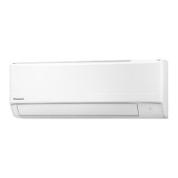
Details the location of controls and components within the indoor unit.
Details the location of controls and components within the outdoor unit.
Details the location of controls and components on the remote control unit.
Provides detailed dimensions for the indoor unit and its remote control.
Provides detailed dimensions for the outdoor unit.
Illustrates the refrigeration cycle for specific indoor/outdoor unit models.
Illustrates the refrigeration cycle for specific indoor/outdoor unit models.
Shows the block diagram for specific indoor/outdoor unit models.
Shows the block diagram for specific indoor/outdoor unit models.
Details wiring connections for the indoor unit.
Details wiring connections for the outdoor unit.
Presents the electronic circuit diagram for the indoor unit.
Presents the electronic circuit diagram for the outdoor unit.
Illustrates the printed circuit board layout for the indoor unit.
Illustrates the printed circuit board layout for the outdoor unit.
Guidelines for choosing the optimal installation site for the unit.
Instructions for installing the indoor unit, including mounting and piping.
Instructions for installing the outdoor unit, including mounting and piping.
Explains fundamental operational principles and inverter control logic.
Details fan speed settings and operation modes for the indoor unit.
Describes the operational behavior of the outdoor fan motor.
Explains the control mechanisms for vertical and horizontal airflow direction.
Details the functionality of ON and OFF timers for unit scheduling.
Describes the sleep mode for enhanced comfort during nighttime use.
Explains the unit's behavior following a power interruption event.
Details the meaning and function of the LED indicators on the unit.
Describes the quiet operation mode for reduced noise levels in cooling.
Describes the quiet operation mode for reduced noise levels in heating.
Explains the powerful mode for rapid temperature adjustment and faster comfort.
Covers general protection mechanisms applicable to all operating modes.
Details protection measures specific to cooling and soft dry modes.
Details protection measures specific to heating operations.
Explains operations using the Auto OFF/ON button for servicing purposes.
Describes how to activate and deactivate the heat-only operating mode.
Details functions related to remote control buttons for settings and modes.
Provides guidance on diagnosing refrigeration cycle malfunctions.
Explains correlations between operating conditions and system parameters.
Details the self-diagnosis function for identifying unit malfunctions.
Lists error codes, their causes, and check locations for troubleshooting.
Provides step-by-step methods for performing self-diagnosis.
Procedures for disassembling and assembling the indoor unit for specific models.
Procedures for disassembling and assembling the indoor unit for a specific model.
Step-by-step guide for removing the outdoor unit's electronic controller.
Presents performance data for cooling mode across various conditions.
Presents performance data for heating mode across various conditions.
Shows how cooling performance varies with outdoor air temperature.
Shows how heating performance varies with outdoor air temperature.
Provides correction factors for capacity based on piping length.
Provides exploded views and parts lists for the indoor unit.
Provides exploded views and parts lists for the outdoor unit.
| Brand | Panasonic |
|---|---|
| Model | CS-BE35TKE |
| Category | Air Conditioner |
| Language | English |


 Loading...