Do you have a question about the Panasonic CS-BE35TKE-1 and is the answer not in the manual?
Discusses general warnings, cautions, and prohibited actions for safe servicing.
Provides detailed technical specifications for different models including cooling, heating, and electrical data.
Highlights inverter technology, environment protection, long piping, remote control, quality, operation, and serviceability.
Identifies and describes controls and components located on the indoor unit.
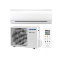
Identifies and describes controls and components located on the outdoor unit.
Details the buttons and functions of the remote control for operating the unit.
Provides physical dimensions and layout details for the indoor unit and remote control.
Provides physical dimensions and layout details for the outdoor unit.
Illustrates the flow of refrigerant during cooling and heating operations.
Depicts the overall electrical system architecture of the air conditioner unit.
Shows the detailed wiring connections for the indoor unit's electrical components.
Shows the detailed wiring connections for the outdoor unit's electrical components.
Provides the electronic circuit schematic for the indoor unit.
Provides the electronic circuit schematic for the outdoor unit.
Shows the layout of components on the main printed circuit board for the indoor unit.
Shows the layout of components on the indicator and receiver printed circuit board for the indoor unit.
Illustrates the main printed circuit board layout for the outdoor unit.
Guidelines for choosing optimal installation locations for indoor and outdoor units.
Step-by-step instructions for mounting and installing the indoor unit and its components.
Detailed steps for installing the outdoor unit, including piping and connections.
Explains the fundamental operation modes like Cooling, Soft Dry, and Heating.
Describes the operation and speed control of the indoor and outdoor fan motors.
Details how to control vertical and horizontal airflow direction.
Explains the functionality of ON/OFF timers and sleep mode for user comfort.
Covers Quiet Operation, Powerful Mode, and Indication Panel functions.
Outlines restart control, total running current, and IPM overheating prevention.
Details protection mechanisms during cooling and soft dry operations like freeze and dew prevention.
Explains protection controls specific to heating operations, including overload and cold draught prevention.
Describes how to activate auto operation, test run, and change remote control settings.
Details the activation, deactivation, and comparison of heat-only operation modes.
Explains how to use SET, RESET buttons and special setting modes on the remote control.
Guides on diagnosing issues related to the refrigeration cycle, pressure, and current.
Instructions on how to use the self-diagnosis function to identify error codes.
A comprehensive table listing error codes, their causes, and check locations.
Provides detailed troubleshooting steps for various error codes like H11, H12, H14, etc.
Step-by-step procedures for disassembling the indoor unit components like front grille and fan.
Procedures for removing the electronic controller from the outdoor unit.
Presents performance data for cooling mode under various temperature conditions.
Presents performance data for heating mode under various temperature conditions.
Graphs showing the relationship between outdoor air temperature and unit performance in cooling.
Graphs showing the relationship between outdoor air temperature and unit performance in heating.
Correction factors for unit performance based on the length of the refrigerant piping.
An exploded view diagram and list of replacement parts for the indoor unit.
An exploded view diagram and list of replacement parts for the outdoor unit.
| Cooling Capacity | 3.5 kW |
|---|---|
| Heating Capacity | 4.0 kW |
| Power Supply | 220-240 V, 50 Hz |
| Refrigerant | R32 |
| Energy Efficiency Class (Cooling) | A++ |
| Energy Efficiency Class (Heating) | A+ |
| Type | Air Conditioner |
| Indoor Unit Noise Level | 21 dB (Low) |
| Dimensions (Outdoor Unit) | 780 x 540 x 285 mm |
| Noise Level (Indoor) | 21 dB (Low) |
| Outdoor Unit Dimensions (W x H x D) | 780 x 540 x 285 mm |