42
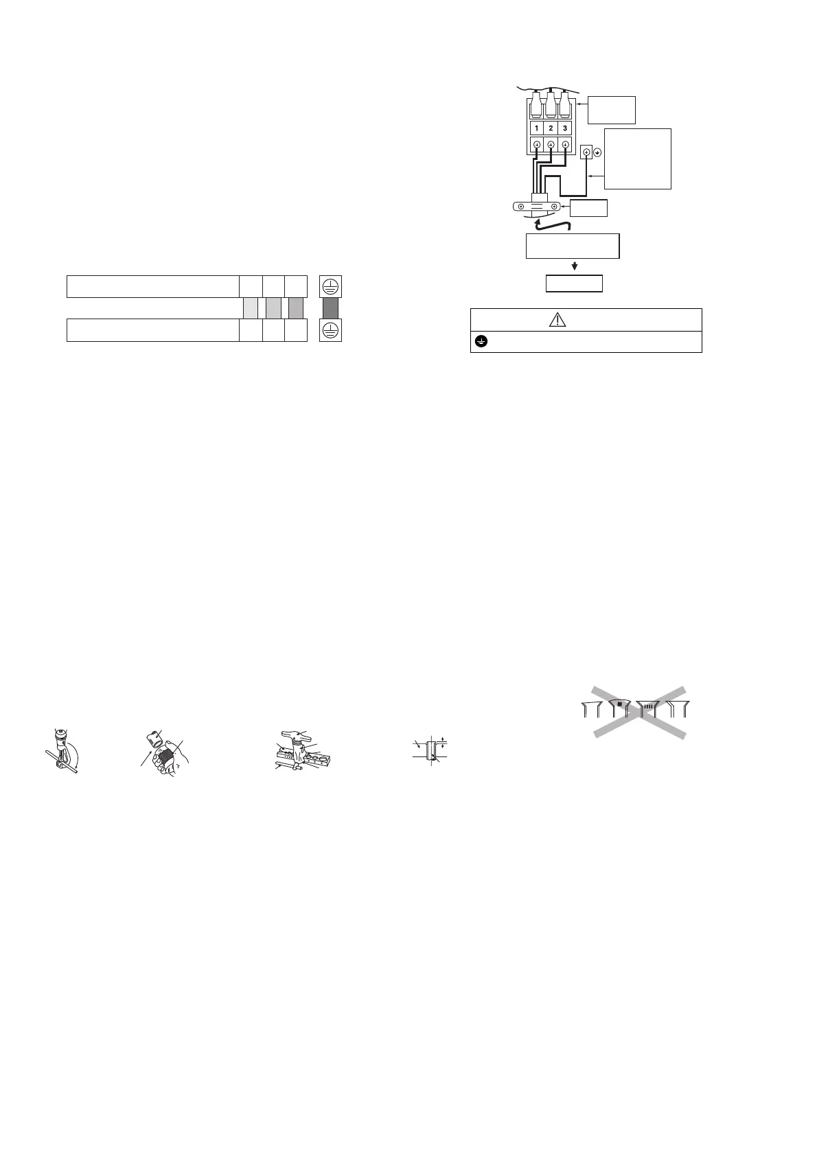
11.3.4 Connect the Cable to the Outdoor Unit
1 Remove the control board cover from the unit
by loosening the screw.
2 Connection cable between indoor unit and
outdoor unit shall be approved
polychloroprene sheathed 4 x 1.5 mm
2
(3/4 ~ 1.5HP) or 4 x 2.5 mm
2
(2.0HP) flexible
cord, type designation 60245 IEC 57 or
heavier cord. Do not use joint connection
cable. Replace the wire if the existing wire
(from concealed wiring, or otherwise) is too
short. Allowable connection cable length of
each indoor unit shall be 30 mm or less.
3 Secure the cable onto the control board with
the holder.
4 Attach the control board cover back to the
original position with screw.
5 For wire stripping and connection requirement,
refer to instruction 11.2.4.1 of indoor unit.
WARNING
This equipment must be properly earthed.
Earth wire shall be Yellow/Green (Y/G) in colour
and longer than other AC wires for safety reason.
11.3.5 Piping Insulation
1 Please carry out insulation at pipe connection portion as mentioned in Indoor/Outdoor Unit Installation
Diagram. Please wrap the insulated piping end to prevent water from going inside the piping.
2 If drain hose or connecting piping is in the room (where dew may form), please increase the insulation by
using POLY-E FOAM with thickness 6 mm or above.
11.3.6 Cutting and Flaring the Piping
1 Please cut using pipe cutter and then remove the burrs.
2 Remove the burrs by using reamer. If burrs is not removed, gas leakage may be caused. Turn the piping end
down to avoid the metal powder entering the pipe.
3 Please make flare after inserting the flare nut onto the copper pipes.
Terminals on the outdoor unit 1 2 3
Colour of wires
Terminals on the indoor unit 1 2 3
Earth Wire
longer than
others AC
wires for
safety reason
Terminal
Board
Holder
Indoor and outdoor
cable connection
Indoor Unit
When properly fl ared, the internal surface of the
fl are will evenly shine and be of even thickness.
Since the fl are part comes into contact with the
connections, carefully check the fl are fi nish.
Improper fl aring
Inclined Surface
damaged
Cracked Uneven
thickness
1. To cut 2. To remove burrs 3. To fl are
Bar
Red arrow mark
Handle
Core
Yoke
Clamp handle
Bar
0 – 0.5 mm
Copper pipe
Reamer
Point down
Pipe
 Loading...