Applicable piping kit
CZ-4F5, 7, 10AN (C18BK, A18BK, V18BK, W18BK)
CZ-52F5, 7, 10AN (C24BK, A24BK, XC24BK, V24BK, W24BK)
SELECT THE BEST LOCATION
INDOOR UNIT
•
There should not be any heat source or steam near the
unit.
•
There should not be any obstacles blocking the air
circulation.
•
A place where air circulation in the room is good.
•
A place where drainage can be easily done.
•
A place where noise prevention is taken into
consideration.
•
Do not install the unit near the door way.
•
Ensure the spaces indicated by arrows from the wall,
ceiling, fence or other obstacles.
•
Recommended installation height for indoor unit shall be
at least 2.3 m.
OUTDOOR UNIT
•
If an awning is built over the unit to prevent direct
sunlight or rain, be careful that heat radiation from the
condenser is not obstructed.
•
There should not be any animal or plant which could be
affected by hot air discharged.
•
Keep the spaces indicated by arrows from wall, ceiling,
fence or other obstacles.
•
Do not place any obstacles which may cause a short
circuit of the discharged air.
•
If piping length is over 7.5m, additional refrigerant
should be added as shown in the table.
Piping size Rated
Length
(m)
Max.
Elevation
(m)
Max.
Piping
Length
(m)
Additional
Refrigerant
(g/m)
Model Gas Liquid
C18BK,
V18BK
1/2” 1/4” 5 20 25 20
C24BK,
V24BK,
XC24BK
5/8” 1/4” 5 20 25 30
A18BK,
W18BK
1/2” 1/4” 5 20 25 20
A24BK,
W24BK
5/8” 1/4” 5 20 25 30
Example: For A24BK
If the unit will be installed at a 10m distance, the quantity of
additional refrigerant should be 75g...(10 - 7.5)m × 30g/m = 75g
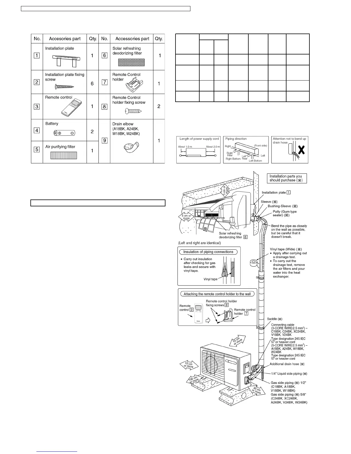
Indoor/Outdoor Unit Installation Diagram
•
This illustration is for explanation purposes only.
The indoor unit will actually face a different way.
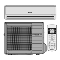
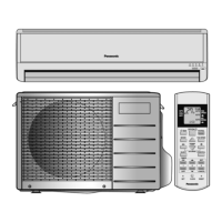
Attached accessories
36
CS-C18BKP CU-C18BKP5 / CS-C18BKP CU-C18BKP6 / CS-C24BKP CU-C24BKP5 / CS-C24BKP CU-C24BKP6
 Loading...