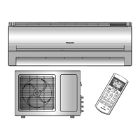
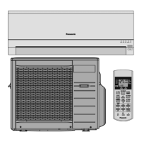
10.6. Outdoor unit
10.6.2. INSTALL THE OUTDOOR UNIT
• After selecting the best location, start installation according
to Indoor/Outdoor Unit Installation Diagram.
1. Fix the unit on concrete or rigid frame firmly and horizontally
by bolt nut. (ø10 mm).
2. When installing at roof, please consider strong wind and
earthquake. Please fasten the installation stand firmly with
bolt or nails.
10.6.3. CONNECTING THE PIPING
Connecting The Piping To Indoor Unit
Please make flare after inserting flare nut (locate at joint portion
of tube assembly) onto the copper pipe. (In case of using long
piping)
Connect the piping
• Align the center of piping and sufficiently tighten the flare
nut with fingers.
• Further tighten the flare nut with torque wrench in specified
torque as stated in the table.
Connecting the Piping to Outdoor Unit
1. Align the center of the piping and sufficiently tighten the
flare nut with fingers.
2. Finally, tighten the flare nut with torque wrench until the
wrench clicks.
• When tightening the flare nut with torque wrench,
ensure the direction for tightening follows the arrow on
the wrench.
MODEL Piping size (Torque)
Gas Liquid
CS-C9DKZW 3/8” (42 N.m) 1/4” (18 N.m)
10.6.1. SELECT THE BEST LOCATION
(Refer to “Select the best location” section)
Caution
The CU-3C20DKH/C9DKZW have different cooling capacities depending on the connection to A
1
,A
2
and/or B on CU-
3C20DKH individually.
(Refer to SPECIFICATIONS on CATALOG)
1. The Cooling Capacity of Indoor Unit connecting “B” on CU-3C20DKH (Called B unit) is different from that of A
1
and A
2
Units.
2. A
1
and A
2
Units share the same compressor, their cooling capacities thus change depending on whether one, the other,
or both of the units is in use.
3. Reflect the B or A (A
1
and/or A
2
) on the Indoor Unit for later reference.
43
CS-C9DKZW CU-2C18DKH / CS-C9DKZW CU-3C20DKH