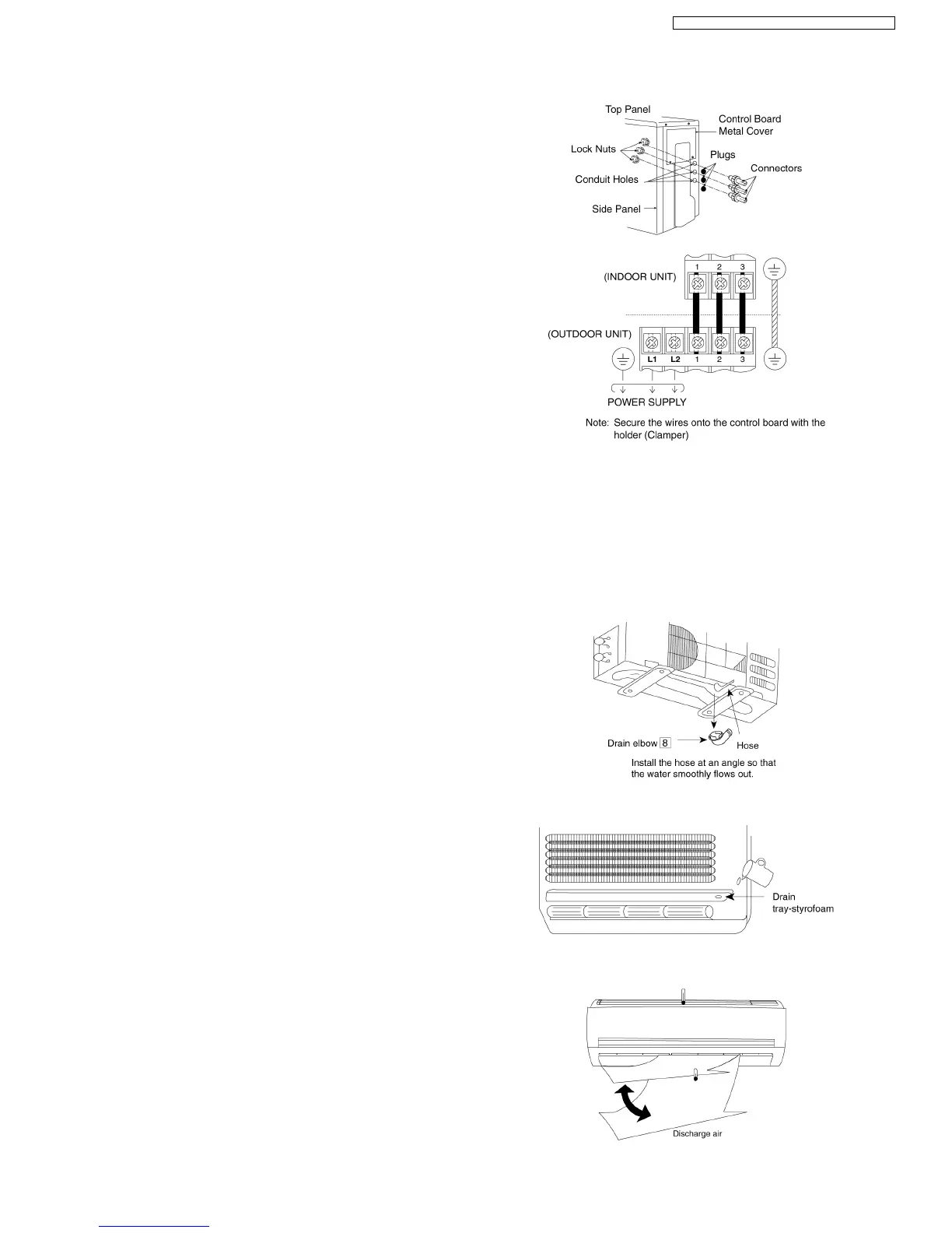
1. Remove Top panel.
2. Remove Control Board Cover.
3. Remove Plugs.
4. Fix the conduit connectors to the conduit holes with lock-
nuts, then secure them.
5. Connecting wire between indoor unit and outdoor unit
should be UL listed or CSA approved 4 x AWG16 wire.
6. Secure the wire onto the control board with the holder
(clamper).
7. Wire connection to the power supply (208/230V 60Hz)
through circuit breaker.
• Connect the UL listed or CSA approved wires (AWG12)
to the terminal board, and connect to other end of the
wires to circuit breaker.
8. After completing wiring connections, reattach the control
board cover and the top panel to the original position with
the screws.
• If a drain elbow is used, the unit should be placed on a
stand which is taller than 1-3/16”.
• If the unit is used in an area where temperature falls below
32°F for 2 or 3 days in succession, it is recommended not
to use a drain elbow, as the drain water freezes and the fan
will not rotate.
• Open front panel and remove air filters.
(Drainage checking can be carried out without removing the
front grille.)
• Pour a glass of water into the drain tray-styrofoam.
• Ensure that water flows out from drain hose of the indoor
unit.
• Operate the unit at cooling operation mode for fifteen
minutes or more.
• Measure the temperature of the intake and discharge air.
• Ensure the difference between the intake temperature and
the discharge is more than 46.4°F.
9.3.4. OUTDOOR UNIT ELECTRICAL WIRING
9.3.5. PIPE INSULATION
1. Please carry out insulation at pipe connection portion as mentioned in Indoor/Outdoor Unit Installation Diagram. Please wrap
the insulated piping end to prevent water from going inside the piping.
2. If drain hose or connecting piping is in the room (where dew may form), please increase the insulation by using POLY-E FOAM
with thickness 1/4” or above.
9.3.6. DISPOSAL OF OUTDOOR UNIT DRAIN WATER
9.3.7. CHECK THE DRAINAGE
9.3.8. EVALUATION OF THE PERFORMANCE
25
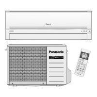
CS-E18EKU CU-E18EKU / CS-E21EKU CU-E21EKU