46
11.3 Outdoor Unit
11.3.1 Install the Outdoor Unit
After selecting the best location, start installation according to Indoor/Outdoor Unit Installation Diagram.
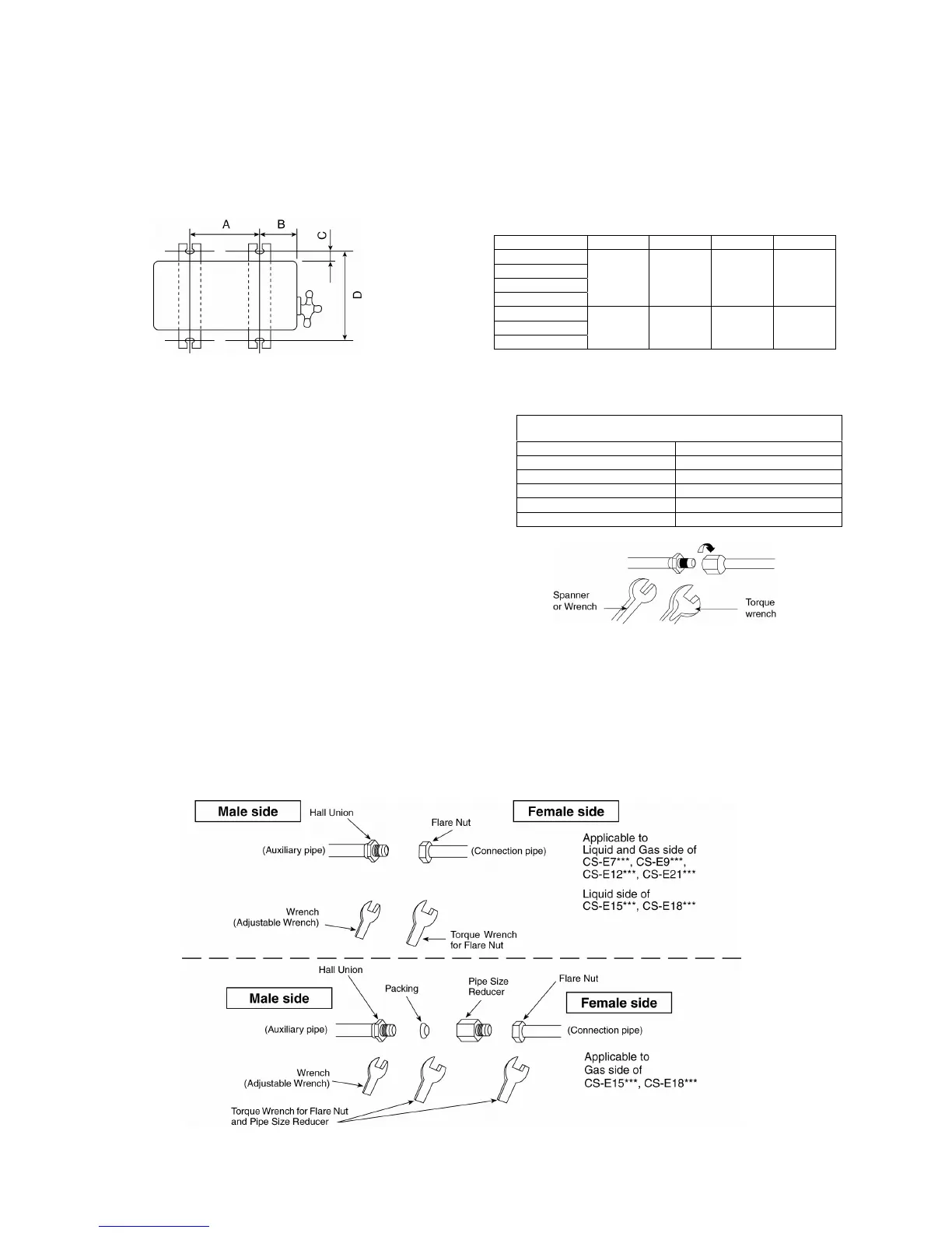
1 Fix the unit on concrete or rigid frame firmly and horizontally by bolt nut (ø10 mm).
2 When installing at roof, please consider strong wind and earthquake. Please fasten the installation stand
firmly with bolt or nails.
Model A B C D
E7***
E9***
E12***
E15***
570 mm 105 mm 18.5 mm 320 mm
E18***
E24***
E28***
613 mm 131 mm 16 mm 360.5 mm
11.3.2 Connect the Piping
Connecting the Piping to Indoor
Please make flare after inserting flare nut (locate at
joint portion, of tube assembly) onto the copper pipe.
(In case of using long piping)
Connect the piping
Align the center of piping and sufficiently tighten
the flare nut with fingers.
Further tighten the flare nut with torque wrench in
specified torque as stated in the table.
Connecting the Piping to Outdoor
Decide piping length and then cut by using pipe cutter.
Remove burrs from cut edge.
Make flare after inserting the flare nut (locate at valve)
onto the copper pipe.
Align center of piping to valves and then tighten with
torque wrench to the specified torque as stated in the
table.
Connecting the Piping to Outdoor Multi
Decide piping length and then cut by using pipe cutter. Remove burrs from cut edge. Make flare after inserting the
flare nut (locate at valve) onto the copper pipe.
Align center of piping to valve and then tighten with torque wrench to the specified torque as stated in the table.
Do not overtighten, overtightening may cause gas leakage.
Piping Size Torque
6.35 mm (1/4”) [18 N•m (1.8 kgf.m)]
9.52 mm (3/8”) [42 N•m (4.3 kgf.m)]
12.7 mm (1/2”) [55 N•m (5.6 kgf.m)]
15.88 mm (5/8”) [65 N•m (6.6 kgf.m)]
19.05 mm (3/4”) [100 N•m (10.2 kgf.m)]