29
11.2.4. Connect The Cable To The Indoor Unit
The power supply cable and indoor unit and outdoor unit connecting cable can be connected without removing the front grille.
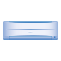
1 Install the indoor unit on the installing holder that mounted on the wall,
2 Open the front panel and grille door by loosening the screw.
3 Cable connection to the power supply through Isolating Devices (Disconnecting means).
• Connect the approved polychloroprene sheathed power supply cord 3 x 1.5 mm
2
(1.0~1.5HP) or 3 x 2.5 mm
2
(2.0~2.5HP),
type designation 245 IEC 57 or heavier cord to the terminal board, and connect the others end of the cable to Isolating
Devices (Disconnecting means).
• Do not use joint power supply cord. Replace the wire if the existing wire (from concealed wiring, or otherwise) is too short.
• In unavoidable case, joining of power supply cord between isolating devices and terminal board of air conditioner shall be
done by using approved socket and plug rated 15/16A (1.0~1.5HP) or 16A (2.0HP) or 20A (2.5HP). Wiring work to both
socket and plug must follow to national wiring standard.
4 Bind all the power supply cord lead wire with tape and route the power supply cord via the left escapement.
5 Connection cable between indoor unit and outdoor unit shall be approved polychloroprene sheathed 3 x 1.5 mm
2
(1.0 ~
1.5HP) or 3 x 2.5 mm
2
(2.0 ~ 2.5HP) flexible cord, type designation 245 IEC 57 or heavier cord. Do not use joint connection
cable. Replace the wire if the existing wire (from concealed wiring, or otherwise) is too short.
6 Bind all the indoor and outdoor connecting cable with tape and route the connecting cable via the right escapement.
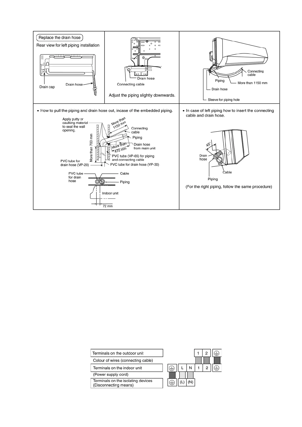
7 Remove the tapes and connect the power supply cord and connecting cable between indoor unit and outdoor unit according
to the diagram below.
8 Secure the power supply cord and connecting cable onto the control board with the holder.