Do you have a question about the Panasonic CS-PC12TKF and is the answer not in the manual?
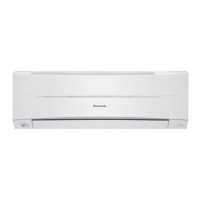
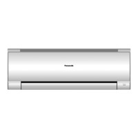
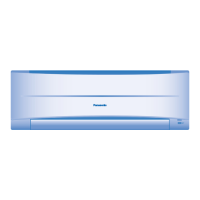
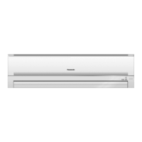
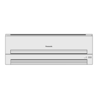
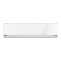
Identifies control locations and indicators on the indoor unit, including airflow louvers and receiver.
Shows the air inlet and outlet locations on the outdoor unit for component identification.
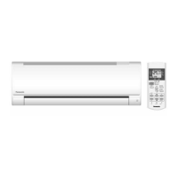
Details the layout and function of buttons and the display on the remote control unit.
Provides detailed measurements and diagrams for the indoor unit, including remote control.
Presents detailed measurements and diagrams for the outdoor units (CU-PC12TKF, CU-PC18TKF, CU-PC24TKF).
Illustrates the electrical block diagram for the CS-PC12TKF and CU-PC12TKF models.
Shows the electrical block diagram for the CS-PC18TKF and CU-PC18TKF models.
Presents the electrical block diagram for the CS-PC24TKF and CU-PC24TKF models.
Details the wiring connections and component resistances for the CS-PC12TKF and CU-PC12TKF.
Outlines the wiring connections and component resistances for the CS-PC18TKF and CU-PC18TKF.
Provides wiring connections and component resistances for the CS-PC24TKF and CU-PC24TKF models.
Shows the electronic circuit diagram for the CS-PC12TKF and CU-PC12TKF, including thermistor characteristics.
Presents the electronic circuit diagram for the CS-PC18TKF and CU-PC18TKF, including thermistor characteristics.
Illustrates the electronic circuit diagram for the CS-PC24TKF and CU-PC24TKF, including thermistor characteristics.
Shows the layout of the main and indicator/receiver PCBs for the indoor unit.
Guides on choosing optimal locations for indoor and outdoor units, considering factors like airflow and obstacles.
Covers fixing the installation plate, drilling holes, embedding piping, and connecting cables to the indoor unit.
Details installing the outdoor unit, connecting piping, evacuation, air purging, and piping insulation steps.
Explains how to set and the behavior of the cooling operation mode, including time diagrams.
Describes the soft dry operation for dehumidification and gentle cooling, including time diagrams.
Details the automatic operation mode, how it judges temperature, and sets operating modes.
Covers fan speed rotation charts, automatic fan speed adjustments, and manual settings.
Explains auto and manual control for vertical and horizontal airflow direction.
Describes JETSTREAM operation for rapid cooling and Quiet operation for reduced noise levels.
Covers ON/OFF timers, sleep mode, random auto restart, and remote control signal sounds.
Details restart controls, time save functions, forced operation, starting current, and freeze prevention.
Explains the control to prevent the indoor heat exchanger from freezing.
Explains protection against compressor reverse rotation during power fluctuations.
Describes the control system to prevent dew formation in the indoor unit's discharge area.
Explains how to activate AUTO, Test Run, and Various Setting modes using the Auto OFF/ON button.
Covers remote control button functions, special settings, and option lists for unit configuration.
Guides on diagnosing issues related to refrigerant pressure, electric current, and temperature differences.
Provides step-by-step instructions for disassembling the indoor unit's front grille, controller, and fan.
Details the disassembly process for the indoor units of CS-PC18TKF and CS-PC24TKF models.
Presents graphical data illustrating thermostat characteristics for cooling and soft dry modes.
Provides performance data graphs for cooling characteristics based on temperature and piping length.
Displays exploded views and lists replacement parts for the indoor units (CS-PC12TKF, CS-PC18TKF, CS-PC24TKF).
Shows exploded views and lists replacement parts for the outdoor units (CU-PC12TKF, CU-PC18TKF, CU-PC24TKF).
| Brand | Panasonic |
|---|---|
| Model | CS-PC12TKF |
| Category | Air Conditioner |
| Language | English |