30
11.2 Indoor Unit
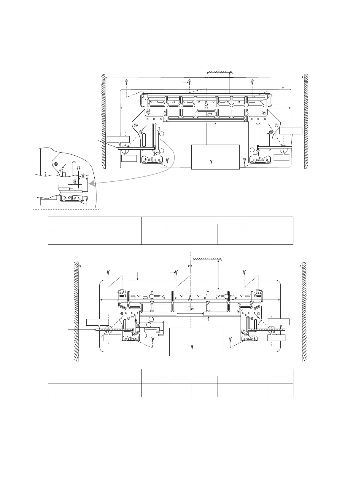
11.2.1 How to Fix Installation Plate
The mounting wall shall be strong and solid enough to prevent it from the vibration.
3 4
B
A
C
C
128 mm
PIPE
HOLE
CENTER
128mm TO
PIPE HOLE
CENTER
A
Ceiling
Wall
Wall
Installation
plate
1
2
screw
More than 1
More than 1
Measuring Tape
Indoor unit
184 mm
128 mm
222 mm
128 mm
More
than 2
PIPE
HOLE
CENTER
PIPE
HOLE
CENTER
128mm TO
PIPE HOLE
CENTER
128mm TO
PIPE HOLE
CENTER
For best strength of
INDOOR unit installation,
it is highly recommended
to locate “
” at 5 position
as shown.
Model
Dimension
1 2 3 4 5 6
PC12*** 470 mm 90 mm 380 mm 420 mm 15 mm 35 mm
3 4
5
6
Ceiling
Wall
Wall
Installation plate
1
2
screw
More than 1
More than
1
Measuring Tape
Indoor unit
More
than 2
For best strength of
INDOOR unit installation,
it is highly recommended
to locate “
” at 5 position
as shown.
256 mm
128 mm
128 mm
256 mm
128 mm
Model
Dimension
1 2 3 4 5 6
PC18***, PC24*** 605 mm 95 mm 550 mm 550 mm 210 mm 260 mm
The center of installation plate should be at more than 1 at right and left of the wall.
The distance from installation plate edge to ceiling should more than 2.
From installation plate center to unit’s left side is 3.
From installation plate center to unit’s right side is 4.
B : For left side piping, piping connection for liquid should be about 5 from this line.
: For left side piping, piping connection for gas should be about 6 from this line.