EasyManua.ls Logo

Panasonic CS-V18CKE User Manual

Panasonic CS-V18CKE
77 pages
To Next Page IconTo Next Page
Page #1 background imageLoading...
Page #1 background image
1 Features 2
2 Functions
3
3 Product Specifications
6
4 Dimensions
10
5 Refrigeration Cycle Diagram
12
6 Block Diagram
13
7 Wiring Diagram
14
8 Operation Details
15
8.1. Indoor Fan Speed Control
15
8.2. Cooling Mode Operation
16
8.3. Soft Dry Mode Operation
20
8.4. Air Circulation Mode Operation
22
8.5. Automatic Mode Operation
22
© 2003 Matsushita Industrial Corp. Sdn. Bhd.
(11969-T). All rights reserved. Unauthorized copying
and distribution is a violation of law.
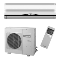
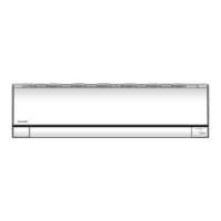
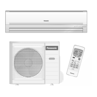
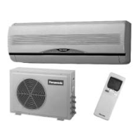
CS-V18CKE CU-V18CKE
CS-V24CKE CU-V24CKE
8.6. Powerful Mode Operation 23
8.7. Random Auto Restart Control
23
8.8. Airflow Direction Control
24
8.9. Delay ON Timer Control
25
8.10. Remote Control Signal Receiving Sound
25
8.11. Ionizer Operation
26
9 Operating Instructions
30
10 Installation Instructions
38
10.1. Safety Precautions
38
10.2. INDOOR UNIT
41
10.3. OUTDOOR UNIT
44
11 Installation and Servicing Air Conditioner Using R410A
48
11.1. OUTLINE
48
Air Conditioner
CONTENTS
Page Page
Order No. MAC0310023C2

Table of Contents

Questions and Answers:

Panasonic CS-V18CKE Specifications

General IconGeneral
TypeSplit System
Cooling Capacity5.0 kW
Power Supply220-240V, 50Hz
Energy Efficiency Ratio (EER)3.21
RefrigerantR410A
Indoor Unit Weight13 kg
Outdoor Unit Weight35 kg
Outdoor Unit Dimensions (W x H x D)780 x 540 x 289 mm

Summary

Features

Functions

Remote Control Operations

Details the operation and settings available via the remote control.

Product Specifications

Dimensions

Indoor and Outdoor Unit Dimensions

Detailed measurements and diagrams for indoor and outdoor units.

Refrigeration Cycle Diagram

Block Diagram

Wiring Diagram

Operation Details

Indoor Fan Speed and Airflow Control

Explains fan speed adjustment and airflow direction control.

Cooling and Soft Dry Modes

Details cooling operations, safety controls, and soft dry mode.

Special Operation Modes

Covers automatic, powerful, auto restart, and ionizer operations.

Timer and Signal Controls

Explains timer functions and remote control signal sounds.

Operating Instructions

Product Overview and Remote Control Use

Visual overview of unit components and basic remote control operation.

Installation Instructions

Installation Safety Precautions

Important safety warnings and precautions for installation.

Indoor Unit Installation Procedures

Step-by-step guide for installing the indoor unit.

Outdoor Unit Installation Procedures

Steps for installing the outdoor unit and connecting piping.

Refrigerant Line Evacuation

Procedure for removing air and moisture from refrigerant lines using a vacuum pump.

Refrigerant Pipe Insulation

Guidance on insulating refrigerant pipes to prevent condensation and heat loss.

R410A Refrigerant: Installation & Servicing

R410A Refrigerant Overview

General information about R410A refrigerant and its properties.

Tools for R410A Piping

Lists essential tools required for R410A refrigerant piping work.

Refrigerant Piping Work Procedures

Details on piping materials and processing for R410A systems.

Installation, Transferring, and Servicing

Procedures for unit installation, transfer, and general servicing.

Servicing Information

Component Removal Procedures

Guides for removing indoor electronic controllers and fan motor.

Troubleshooting Guide

Refrigeration Cycle Troubleshooting

Diagnosing issues related to the refrigeration cycle performance.

Technical Data

Performance Characteristics

Graphs showing cooling performance and thermostat characteristics.

Exploded View (CS-V18CKE/CS-V24CKE)

Replacement Parts List (CS-V18CKE/CS-V24CKE)

Exploded View (CU-V18CKE/CU-V24CKE)

Replacement Parts List (CU-V18CKE/CU-V24CKE)

Electronic Circuit Diagram

Schematic Diagrams (Parts 1-3)

Comprehensive electronic circuit schematics for the unit.

Remote Control and PCB Layouts

Circuit diagram for remote control and PCB print patterns.

Related product manuals