25
11. Installation Instruction
11.1 Outdoor Unit
11.1.1 Select The Best Location
If an awning is built over the unit to prevent direct
sunlight or rain, be careful that heat radiation from
the condenser is not obstructed.
There should not be any animal or plant which
could be affected by hot air discharged.
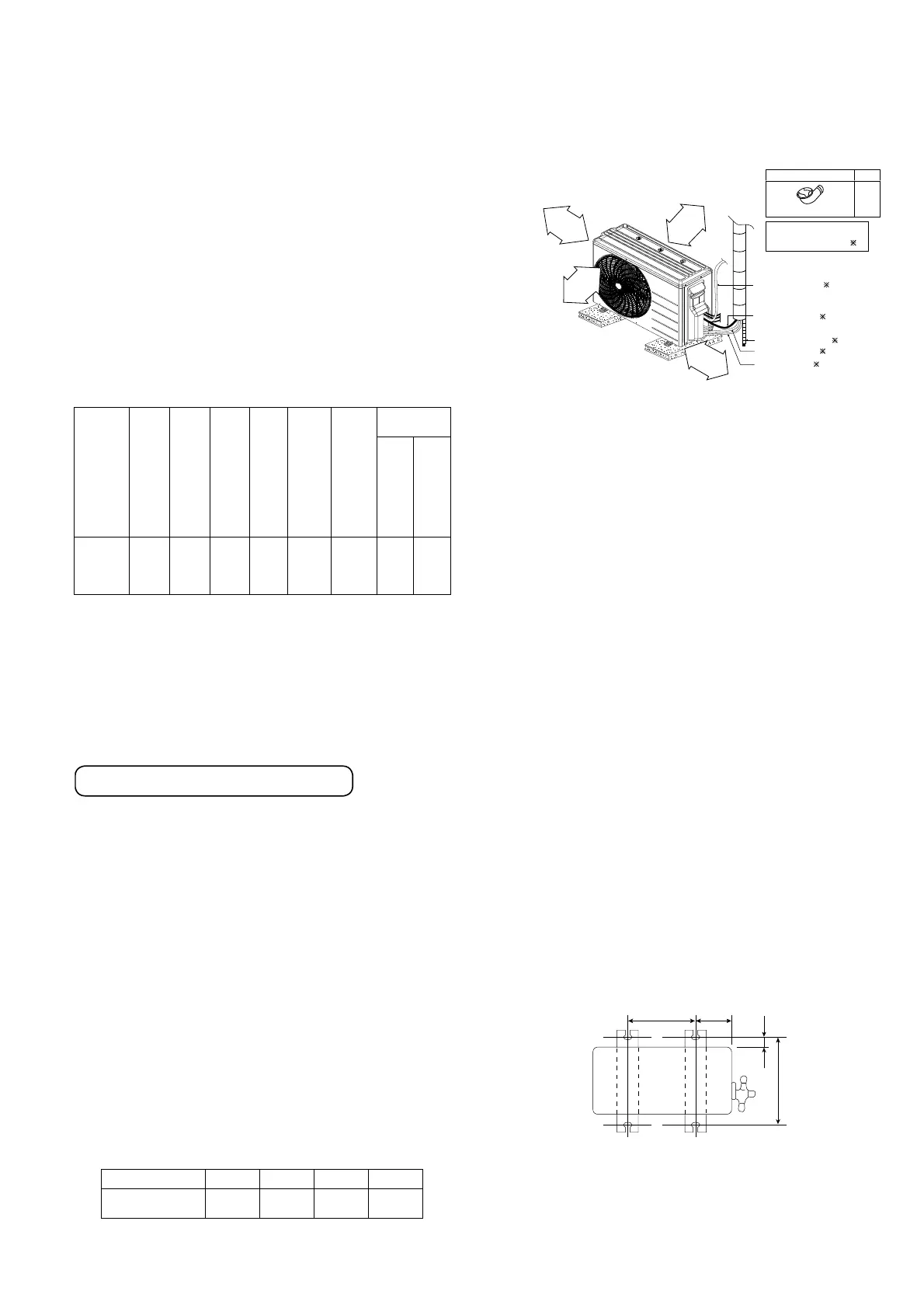
Keep the spaces indicated by arrows from wall,
ceiling, fence or other obstacles.
Do not place any obstacles which may cause a
short circuit of the discharged air.
If piping length is over the [piping length for
additional gas], additional refrigerant should be
added as shown in the table.
Model
Std.
Length
(m)
Min.
Piping
Length
(m)
Max.
Total
Length
(m)
Max.
Eleva-
tion
(m)
Maxi-
mum
Total
Piping
Length
for
Add.
Gas
(m)
Additio
-nal
Refrige-
rant
(g/m)
Indoor A
min
(m
2
)
1.8 m
for
wall
moun-
ted
2.5 m
for
wall
moun-
ted
CU-
2TZ41***,
CU-
2TZ50***
5 m /
indoor
unit
3 m /
indoor
unit
30 10 20 15 1.05 0.54
Note:
(1) It is possible to extend the piping length of one unit
up to 20 meters.
However, the total piping length must not exceed
30 meters.
(2) If the length exceeds 20 meters, refrigerant of 15g
per meter must be added.
A
min
= (m
c
/ (2.5 x (LFL)
(5/4)
x h
0
)) ²
A
min
= Required minimum room area, in m
2
m
c
= Refrigerant charge amount in appliance, in kg
LFL = Lower flammable limit (0.306 kg/m
3
)
h
0
= Installation height of the appliance
: (1.8 m for wall mounted is standard reference
installed height)
: (2.5 m for wall mounted is recommended
installed height give by manufacturer)
Installation parts you
should purchase (
)
Attached accessories Qty
1
Drain elbow
Power supply cord (
)
Gas side piping (
)
Liquid side piping (
)
Connection cable (
)
Additional drain hose (
)
1
0
0
m
m
o
r
m
o
r
e
1
0
0
0
m
m
o
r
m
o
r
e
1
0
0
m
m
o
r
m
o
r
e
3
0
0
m
m
o
r
m
o
r
e
•
This illustration is for
explanation purposes only.
11.1.2 Install The Outdoor Unit
After selecting the best location, start installation
to Indoor/Outdoor Unit Installation Diagram.
1. Fix the unit on concrete or rigid frame firmly
and horizontally by bolt nut (ø10 mm).
2. When installing at roof, please consider strong
wind and earthquake.
Please fasten the installation stand firmly with
bolt or nails.
Model A B C D
CU-2TZ41***,
CU-2TZ50***,
570 mm 105 mm 18.5 mm 320 mm
AB
C
D



 To Next Page