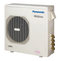
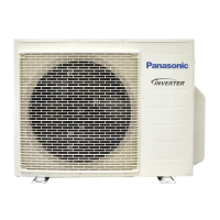
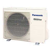
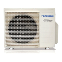
For Outdoor Unit
This air conditioner uses the refrigerant R410A.
External diameter of service port R410A: 5/16"
Split System Air Conditioner
85264190584002 2011 CV6233187853
INSTALLATION INSTRUCTIONS
NOTE
Contents
Page
IMPORTANT!
Please Read Before Starting .................................. 2
1. GENERAL .......................................................... 4
1-1. Tools Required for Installation (not supplied)
1-2. Accessories Supplied with Unit
1-3. Optional Copper Tubing Kit
1-4. Type of Copper Tube and Insulation Material
1-5. Additional Materials Required for Installation
2. INSTALLATION SITE SELECTION ................... 5
2-1. Indoor Unit
2-2. Connecting Indoor Units
2-3. Outdoor Unit
2-4. Baffle Plate for the Outdoor Unit
2-5. Outer Dimensions of Outdoor Unit
2-6. Diagram of Outdoor Unit Installation
3. INSTALLATION PROCESS .............................. 16
3-1. Embedding the Tubing and Wiring
3-2. Use of the Flaring Method
3-3. Flaring Procedure with a Flare Tool
3-4. Caution before Connecting Tubes Tightly
3-5. Tubing Connections
3-6. Insulation of Refrigerant Tubing
3-7. Taping the Tubes
3-8. Finishing the Installation
4. AIR PURGING................................................... 19
Air Purging with a Vacuum Pump (for Test Run)
Pump Down
5. WIRING INSTRUCTIONS ................................ 22
5-1. General Precautions on Wiring
5-2. Recommended Wire Length and Diameter
5-3. Wiring System Diagram
5-4. How to Connect Wiring to the Terminal
5-5. Wiring Instructions for the Outdoor Unit
6. TEST RUN......................................................... 26
7. CONNECTING A HOME AUTOMATION
DEVICE ............................................................. 27
8. INSTALLATION CHECK SHEET ...................... 27
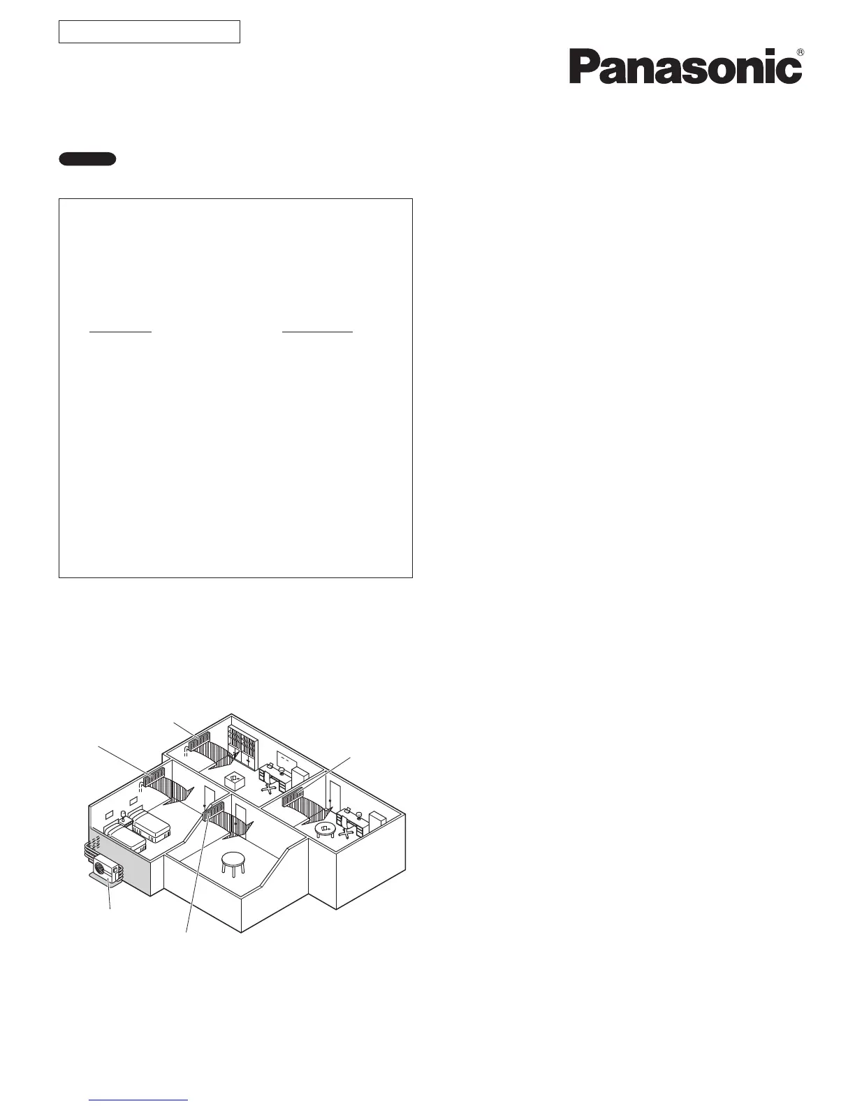
Indoor unit A
Indoor unit B
Indoor unit C
Indoor unit D
Outdoor unit
Combination example
Model Combinations
Combine indoor and outdoor units only as listed
below.
Model No.
Indoor Unit Outdoor Unit
CS-MKE7NKU CU-3KE19NBU
CS-MKE9NKU CU-4KE24NBU
CS-MKE12NKU CU-4KE31NBU
CS-MKE18NKU
CS-MKE24NKU
CS-MKE9NB4U
CS-MKE12NB4U
CS-KE18NB4UW
Power Source:
60 Hz, single-phase, 230 / 208 VAC