12
DVQX2125 (ENG)
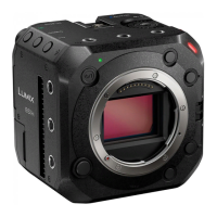
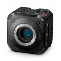
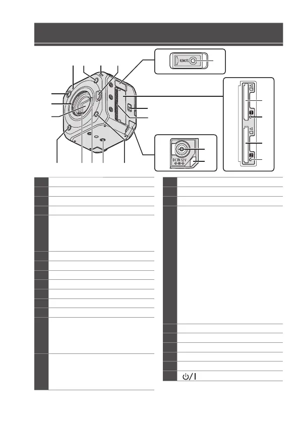
Names of Parts
1
Status indicator
2
Fn button (Fn2)
3
Front tally lamp
4
Lens release button
5
REMOTE terminal cover
• Keep the REMOTE terminal
cover out of reach of children to
prevent swallowing.
6
[REMOTE] terminal
7
Card door
8
Card slot 1
9
Card access light 1
10
Card slot 2
11
Card access light 2
12
Card door release lever
13
Fan outlet (the left side is the inlet)
• The fan outlet for the cooling fan.
Do not block this while the unit is
being used.
14
DC IN terminal cover
• Keep the DC IN terminal cover
out of reach of children to
prevent swallowing.
15
[DC IN 12 V] terminal
16
Cable lock band attachment part
17
Fn button (Fn3)
18
Tripod mount
• There are a total of 11 places for
the tripod mount wherein there
are 3 on the top, the right and
the left and 2 on the bottom.
• The size of the mounting screw
is 1/4-20 UNC (Screw length is
5.5 mm (0.22 inch) or less)
• If you attempt to attach a screw
longer than 5.5 mm (0.22 inch),
you may not be able to securely
fix it in place or it may damage
the camera.
19
Lens lock pin
20
Contact points
21
Fn button (Fn4)
22
Sensor
23
Lens fitting mark
24
[ ] Camera ON/OFF button
1234
5
6
18192021
22
23
24
14
15
16
12
13
17
7
9
8
11
10
 Loading...