Do you have a question about the Panasonic DMP-BD Series and is the answer not in the manual?
Observe lead dress, check protective devices, and perform leakage current checks after servicing.
Caution to replace fuses with the same type and specifications as the original.
Techniques to prevent damage to sensitive components from static electricity during handling and servicing.
Notice regarding special components marked with triangle for safety. Use manufacturer specified parts only.
Precautions for handling the product containing a laser diode, including avoiding direct exposure to the beam.
Description and service cautions for using lead-free solder, including proper melting and handling techniques.
Information on what the service manual contains and does not contain, and parts that are recycle modules.
Detailed specifications for power, media, region code, HDMI, signal system, audio, and dimensions.
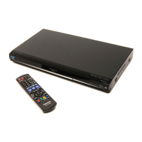
Identification of buttons and indicators on the remote control and the front/rear panel of the unit.
Step-by-step instructions for forcibly ejecting a disc from the BD drive unit when the normal method fails.
List of error codes, their diagnosis contents, description, and monitor/automatic FL display information.
Details on special modes like Rating password, Service Mode, history cleaning, forced disc eject, and aging.
Summary of service mode functions like Error Code Display, ROM Version Display, and Drive check.
List of part numbers, descriptions, quantities, and compatibility for service fixtures and tools.
Flowchart detailing the procedure for disassembling the unit for internal inspection and servicing.
Diagram showing the positions of various PCBs within the unit for reference during disassembly.
Instructions for removing the top case, front panel, and the power/open switch PCBs, including tray door assembly.
Steps for removing the rear panel and the BDP/Digital P.C.B. Module, with a caution about paired replacement.
Instructions for removing the Power P.C.B. and the AV Out P.C.B. (BD80 only) for servicing.
Steps for disassembling the BD drive's upper base assembly and removing the tray.
Instructions for removing pulley gears, belts, and the tray from the BD drive mechanism.
Steps for removing the slide cam, mid gear, drive gear, and loading motor from the BD drive.
Diagrams showing lubrication points and a table of recommended lubricants and their part numbers for BD drive maintenance.
Procedure for cleaning the optical pick-up lens using a cotton swab and ethyl alcohol, followed by a dry cloth.
Overview of service positions for checking and repairing PCBs, including connection details and cautions.
Procedure for checking and repairing the BDP/Digital P.C.B. Module, including connection steps.
Procedure for checking and repairing the AV Out P.C.B. (BD80 only), including connection steps.
Guidelines for replacing parts, including the necessity of updating firmware after replacing the BDP/Digital P.C.B.
Checklist for standard inspection specifications after repairs, covering playback and sound/picture quality.
Explanation of symbols used in schematic diagrams and important safety notices related to components.
Charts providing voltage and waveform data for Audio Out P.C.B. and Power_P P.C.B.
Block diagram illustrating the power supply circuit, showing its components and connections.
Block diagram detailing the flow of analog audio signals from the digital PCB to the output jacks.
Block diagram showing the timer circuit, its controls, and connections to other PCBs.
Diagram showing the interconnections between various PCBs: AV Out, Front, Open SW, BD Drive, Digital, and Power.
Schematic diagram detailing the audio output circuitry, including channel signals and output connectors.
Schematic diagram for the FL display, front panel controls, and associated components.
Schematic diagram for the Power_P PCB, detailing power supply components and regulators (1/2).
Schematic diagram for the front panel controls, including play, stop, pause buttons and LEDs.
Schematic diagram for the Power SW PCB, showing its connections and components.
Schematic diagram for the Open SW PCB, showing its connections and components.
Component and foil side layouts for the Audio Out P.C.B., showing component placement.
Component side layout for the Power_P P.C.B., indicating the placement of all components.
Foil side layout for the Power_P P.C.B., showing copper traces and connections.
Component side layout for the Front P.C.B., showing placement of switches, connectors, and other components.
Component and foil side layouts for the Power SW P.C.B., indicating component placement.
Component and foil side layouts for the Open SW P.C.B., indicating component placement.
Alphabetical list of technical abbreviations used in the manual, covering A through D.
Alphabetical list of technical abbreviations used in the manual, covering E through P.
Alphabetical list of technical abbreviations used in the manual, covering R through T.
Alphabetical list of technical abbreviations used in the manual, covering V through X.
Notes on ordering replacement parts, special component characteristics, and ESD standards.
Exploded view of the unit's frame and casing, showing numbered parts for assembly and replacement.
Exploded view of the BD drive mechanism, detailing components like gears, motors, and trays.
Exploded view of the packing parts and accessories included with the unit, such as remote control and cables.
| Category | Blu-ray Player |
|---|---|
| HDMI Output | Yes |
| USB Port | Yes |
| Ethernet Port | Yes |
| Supported Disc Formats | DVD, CD |
| Wi-Fi | Yes |
| DLNA Certified | Yes |
| Netflix Support | Yes |
| YouTube Support | Yes |