15.8 Removing the right and left arms
TOP PREVIOUS NEXT
(Remove the massager from the chair before beginning the following procedure.)
1. Perform steps 1 to 7 in section, "5. Removing the gear box."
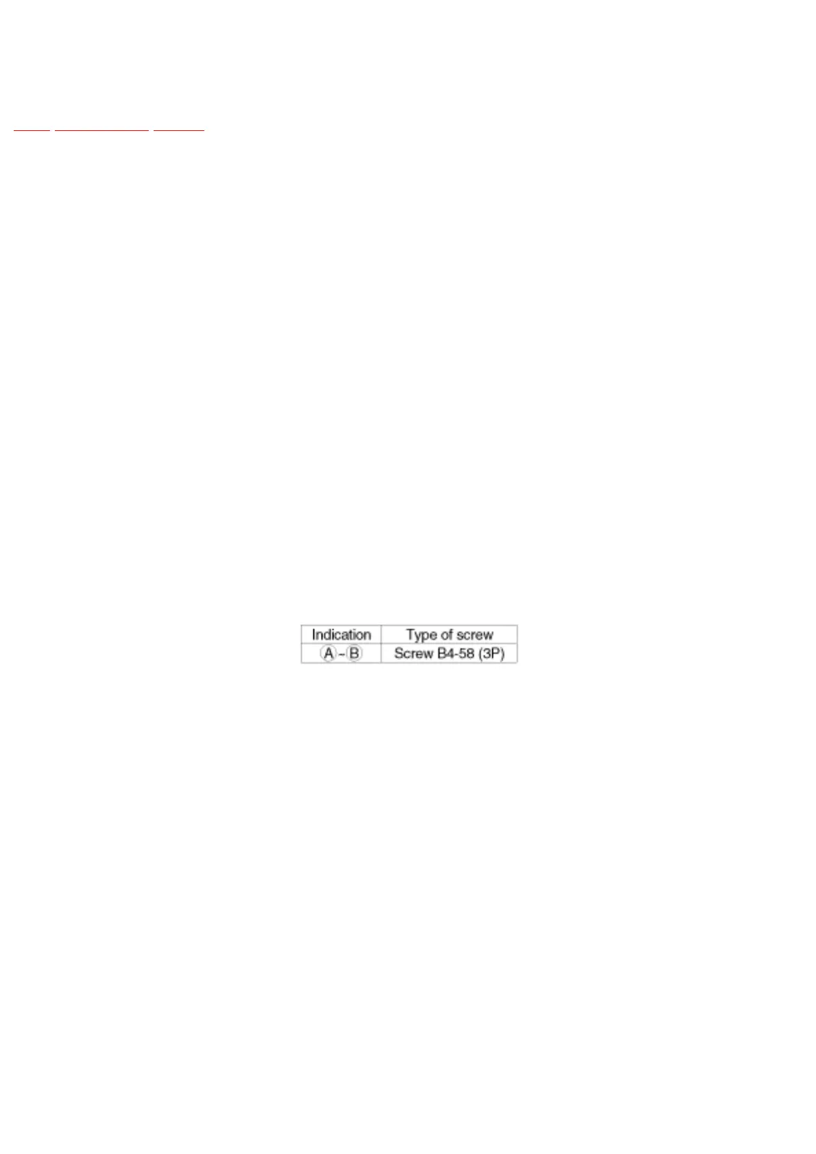
2. Remove screws A and B which connect the gear box and main frame, and remove the main
frame. (When removing the main frame, turn the massage clutch hex nut so that the massage
width is at its minimum.)
3. Remove the up/down shaft bolt of the pinion B block with the box driver, and remove the
pinion B block.
4. Remove the drive pipe bearing, and remove the protrusion detecting plate. (Take care not to
break the protrusion detecting plate.)
5. Using the massage wheel block removing tool, grasp the thrust spring cover and remove the
eccentric shaft stop spring. Next, remove the thrust spring cover and thrust spring, and then
remove the arm (right), eccentric shaft spacer, and arm(left). Please note that disassembly is
possible even without the massage wheel block removing tool.