4.5 Handling Index Registers
4-19
4.5 Handling Index Registers
4.5.1 Index Registers
Index registers are used for indirect specification of values to number (addresses) and
operands in relays and memory areas. (This is also called “index modification”.)
Add the index register to the relay, memory area, or constant you want to modify, and
then write the modifying value (16-bit data) to the index register. The FP0 and FP−e
have two points, IX and IY. The FP0R, FPΣ,FP−X, FP2, FP2SH and FP10SH have 14
points, I0 to ID.
To modify a 32-bit constant, write the 32-bit data to two words of the index register.
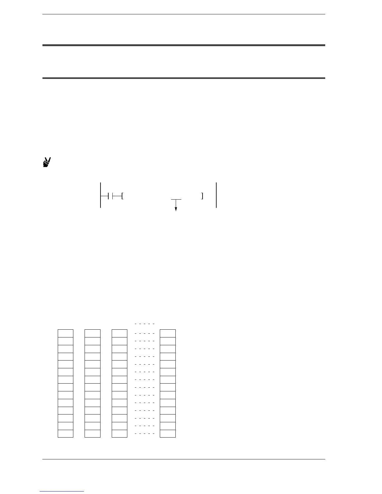
Example: Transferring the contents of data register DT100 to the number
specified by the contents of an index register.
X0
F0 MV, DT100, IXDT0
Base memory area
In this example, the number of the destination data register varies depending on the
contents of IX with DT0 acting as a base. For example, when IX is K10, the destination
will be DT10, and when IX is K20, the destination will be DT20.
In this way, index registers allow the specification of multiple memory areas with a single
instruction, and thus index registers are very convenient when handling large amounts
of data.
Changing banks in an index register of the FP2SH and FP10SH makes it possible to
increase the number of points used in a program from 14 to a maximum of 224 (14
points, 16 banks).
I0
I1
I2
I3
I4
I5
I6
I7
I8
I9
IA
IB
IC
ID
Bank
0
Bank
1
Bank
2
Bank
F






 To Next Page