X Y R L P E T C
modifier
ALT N/A A A A N/A N/A N/A N/A N/A
Explanation of example
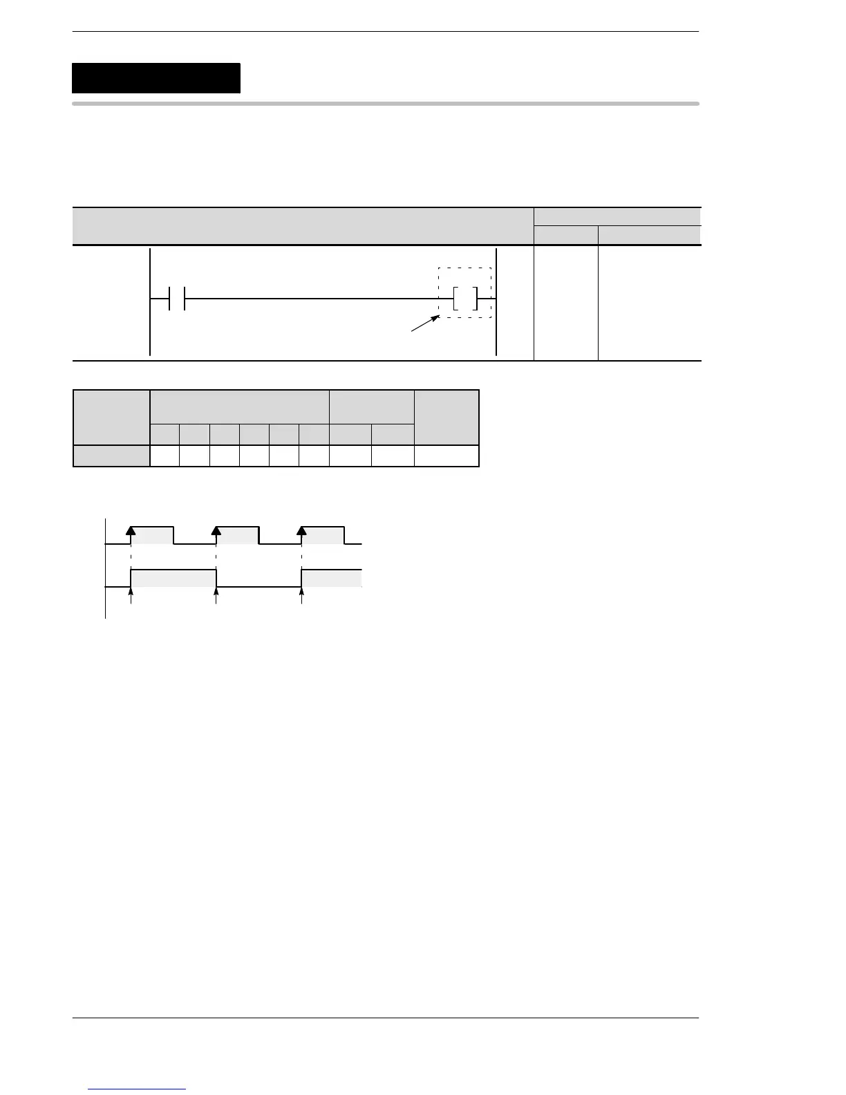
Each time X0 changes from off to on, the on/off state of output Y10 toggles.
X0
Y10
Invert
on
off
on
off
Invert Invert
Description
When the immediately previous processing result changes from off to on, the on/off state of the specified coil
toggles.
The on/off state of the specified coil is held until an ALT instruction specifying that coil rises. (Flip-flop control)
Precautions during programming
During the interval that the input remains on, the output only toggles when the rise occurs, not after that.
When the mode is changed to RUN or the power is turned on in RUN mode such that the input is initially on,
toggling does not occur at the first scan.
When used with instructions which change the order of execution such as MC to MCE and JP to LBL (see
below), take care because the operation of instructions may change depending on the timing of instruction
execution and input.
− MC to MCE instructions
− JP to LBL instructions
− F19 (SJP) to LBL instructions
− LOOP to LBL instructions
− CNDE instruction
− Step ladder instructions
− Subroutine instructions
ALT
Alternative out
 Loading...


