Basic Instructions
2 − 30
Outline When a leading edge of signal is detected, the contact goes on during
that scan only. Leading edge detection is possible at the first scan.
Program example
Boolean
Ladder Diagram
Address Instruction
DFI
X0
0
Y10
Leading edge differential
(initial execution type)
0
1
3
ST X 0
DFI
OT Y 10
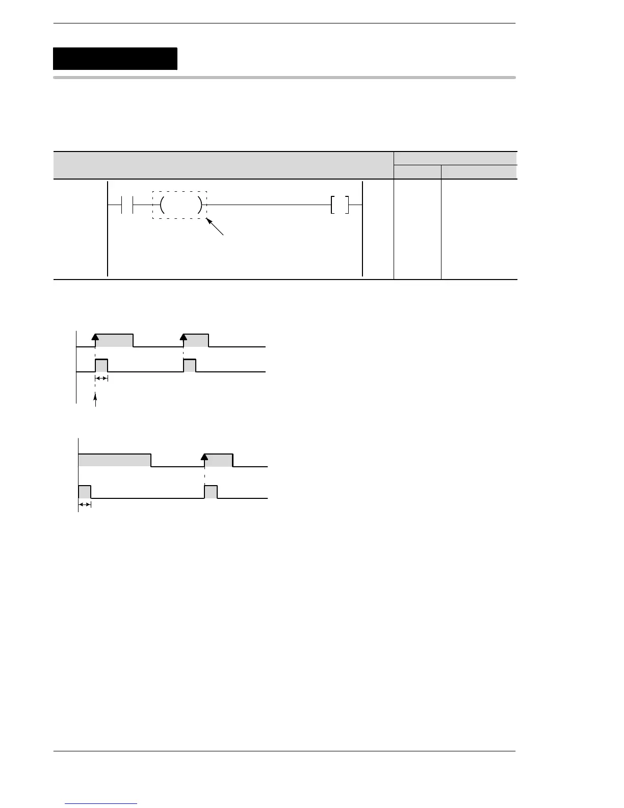
Explanation of example
Output to Y10 takes place for one scan only following a change in X0 from off to on.
When the trigger X0 is met after RUN is begun
X0
Y10
Leading edge
One scan
When the trigger X0 is met before RUN
X0
Y10
One scan
Description
When the trigger (execution condition) changes from off to on, the DFI instruction outputs (differential output)
during the following scan only.
When the trigger (execution condition) is met before RUN is begun, output (differential output) takes place at
the first scan.
There is no limit to the number of times the DFI instruction can be used.
When the mode is changed to RUN or the power is turned on in RUN mode and the trigger (execution
condition) is already met, a DF instruction will not obtain output at the first scan. For this reason, use a DFI
instruction.
DFI
Leading edge differential
(initial execution type)
 Loading...


