Basic Instructions
2 − 32
Outline SET: When the execution conditions have been satisfied, the output is
turned on, and the on status is retained.
RST: When the execution conditions have been satisfied, the output is
turned off, and the off status is retained.
Program example
Boolean
Ladder Diagram
Address Instruction
X0
Y30
20
X1
24
Output destination
S
R
Y30
〈
〈
〈
〈
Reset
Set
20
21
24
25
ST X 0
SET Y 30
ST X 1
RST Y 30
Operands
Relay
Timer/Counter
Contact
Index
Instruction
X Y R
L
(*1)
P
E
(*2)
T C
mo
er
(*3)
SET, RST N/A A A A N/A A N/A N/A A
(*1) This cannot be used with the FP0/FP−e.
(*2) This can be used only with the FP2SH/FP10SH.
(*3) This can be used only with the FP0R/FP2/FP2SH/FP10SH.
O
erand
Relay Timer/Counter Register
Index
register
Constant
Index
WX WY WR WL SV EV DT FL I K H M
modifier
RST N/A A A A A A A A A N/A N/A N/A A
* A word device can be used only by FP2/FP2SH.
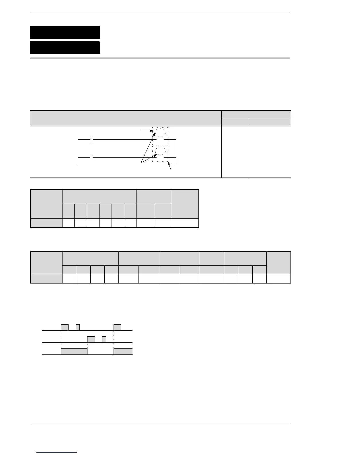
Explanation of example
When X0 turns on, Y30 goes on and holds on.
When X1 turns on, Y30 goes off and stays off.
X0
X1
Y30
on
off
on
off
on
off
Description
The SET instruction executes when the trigger is turned on. Output turns on and holds on even if the trigger’s
state changes.
The RST instruction executes when the trigger is turned on. Output coil turns off and stays off even if the
trigger’s state changes.
You can use relays with the same number as many times as you like with the SET and RST instructions.
(Even if a total check is run, this is not handled as a syntax error.)
SET
RST
Set
Reset
vailable
N/A: Not Available
Phone: 800.894.0412 - Fax: 888.723.4773 - Web: www.clrwtr.com - Email: info@clrwtr.com
 Loading...


