Basic Instructions
2 − 88
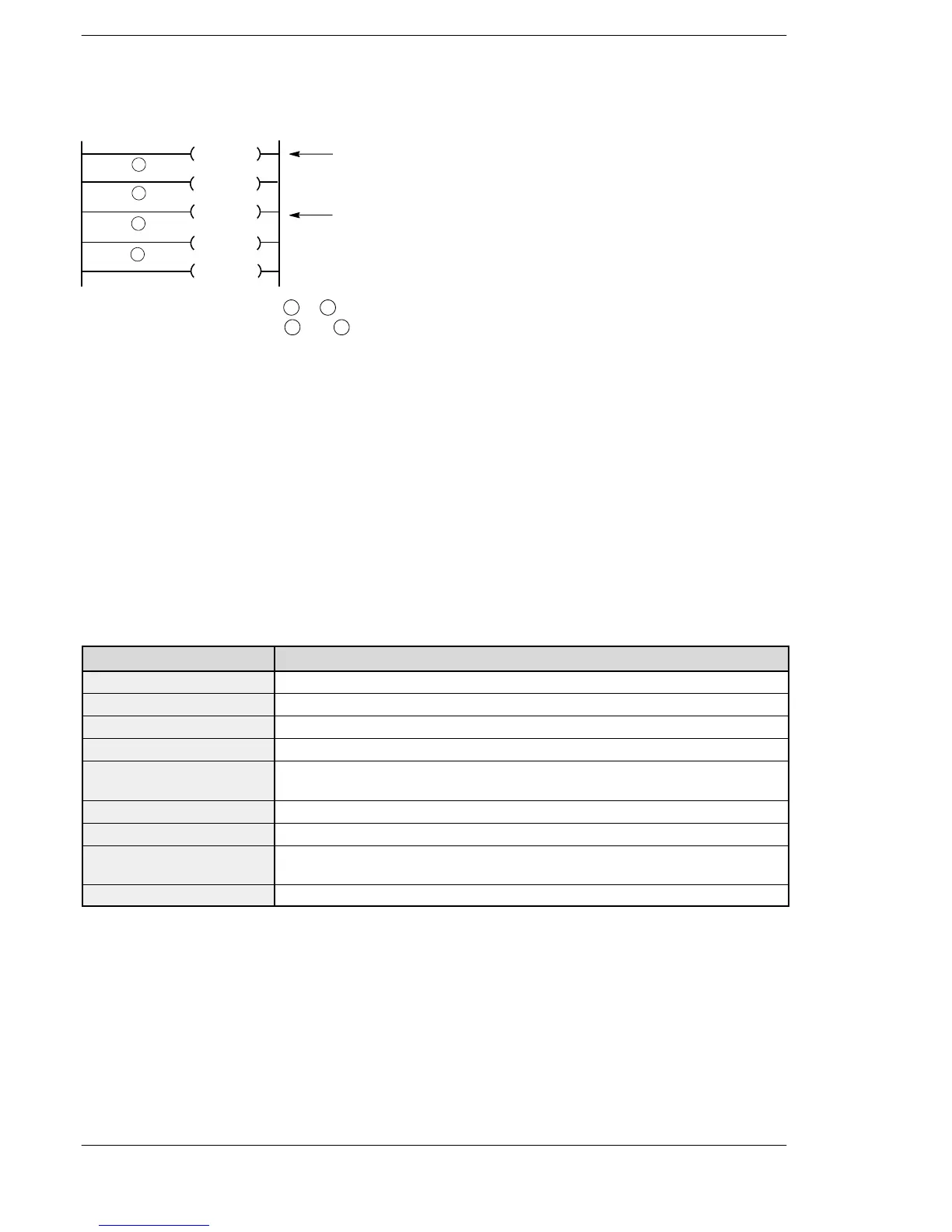
For the FP2/FP2SH/FP10SH, subroutine programs may be constructed with multiple entrances and only
one exit.
SUB 13
RET
SUB 11
SUB 12
SUB 14
CALL11
CALL13
1
2
3
4
When “CALL 11” is executed,
1
to
4
are executed.
When “CALL 13” is executed,
3
and
4
are executed.
You must be careful when you use, in a subroutine, one of the instructions below that is executed by detecting
the leading of execution condition (trigger) such as the differential instruction.
− DF (leading edge differential)
− Count input of CT (counter)
− Count input of F118 (up/down counter)
− Shift input of SR (shift register)
− Shift input of F119 (left/right shift register)
− NSTP (next step)
− Differential execution type high−level instruction (this instruction is specified by P and a number)
When the CALL instruction execution condition (trigger) is off
If the execution condition (trigger) for the CALL instruction is in the off state, the subroutine program is not
executed. (This is the same for CALL instructions within master controls or step ladders.) When the
execution condition (trigger) for the CALL instruction is in the off state, the instructions in the subroutine
operate as follows.
Instruction Operation status
OT Holds the state.
KP Holds the state.
SET Holds the state.
RST Holds the state.
TM Does not perform any timing. If timing is not performed once per scan, the correct
time cannot be guaranteed.
CT Holds the elapsed value.
SR Holds the elapsed value.
DF and DF/ Same as when a differential instruction is used between MC and MCE instructions.
See page 2−57.
Other instructions Not executed.
 Loading...


