Basic Instructions
2 − 104
Specifying control data
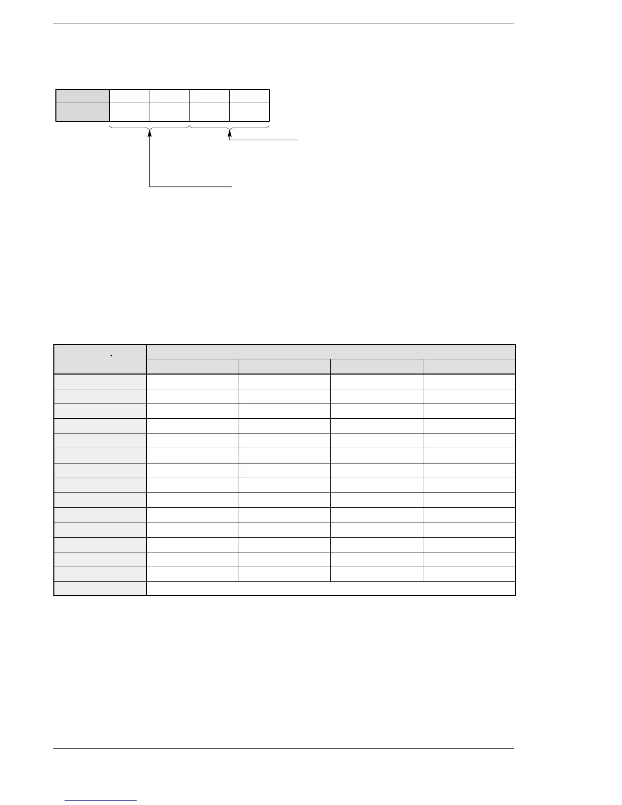
S1: Specifying the control functions and interrupt types
87 43 012 1115
S1
.. .. .. ..
Bit position
Selection of control function
H00: Interrupt “enabled/disabled” control
H01: Interrupt trigger reset control
Interrupt type selection
H00: INT 0 to INT 7
H02: INT 24 (10ms units)
H03: INT 24 (0.5ms units)
Set S1 = H0 to specify enable or disable for the execution of INT0 through INT7.
Set S1 = H100 to clear interrupts INT0 through INT7.
Set S1 = H2 (for units of 10ms) to set the time interval for INT24.
Set S1 = H3 (for units of 0.5ms) to set the time interval for INT24.
Precautions during programming
The inputs that can be actually used as an interrupt input are different depending on the models. (Refer to the
table below.)
Interrupt
Program No.
FP0/FP−e FPΣ/FP0R FP−XRy FP−XTr
INT0 X0 X0 X0 X0
INT1 X1 X1 X1 X1
INT2 X2 X2 X2 X2
INT3 X3 X3 X3 X3
INT4 X4 X4 X4 X4
INT5 X5 X5 X5 X5
INT6 — X6 X6 X6
INT7 — X7 X7 X7
INT8 — — X100 —
INT9 — — X101 —
INT10 — — X102 —
INT11 — — X200 —
INT12 — — X201 —
INT13 — — X202 —
INT24 Periodical interrupt
Note) When using the high−speed counter−initiated interrupt program, the counting performance
of the high−speed counter may be decrement at the moment of the start−up of the interrupt
program.
FP0/FP0R/FP−e/FPΣ/FP−X






 To Next Page