Basic Instructions
2 − 105
S2: Specifying the control of interrupts
1
Enabling or disabling interrupt programs (when S1 = H0 or S1 = H1).
Set the control data in the bit corresponding to the number of the interrupt program that you want to control.
Set the bit corresponding to the number of the program you want to enable to “1.” (INT program disabled.)
Set the bit corresponding to the number of the program you want to disable to “0.” (INT program enabled.)
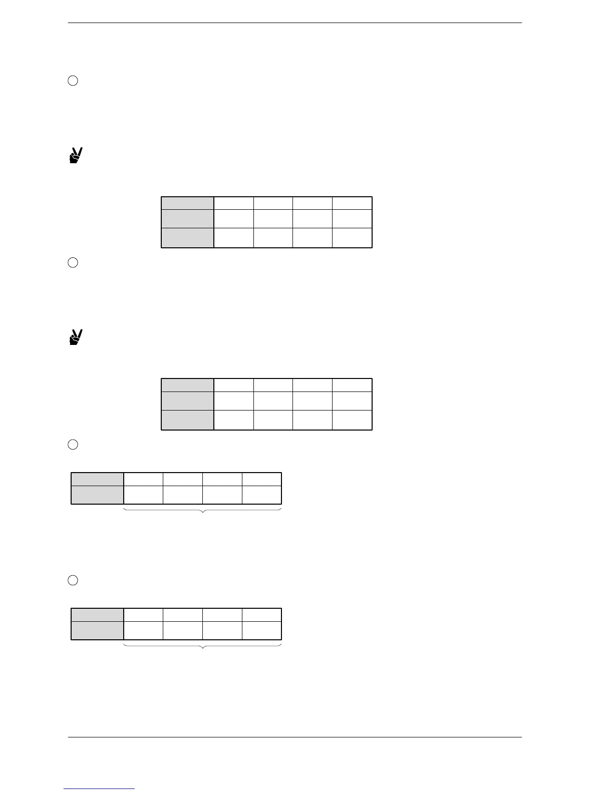
Example: When specified so that the interrupt programs INT1 and INT2 are
enabled, and INT0 and INT3 to 13 are inhibited
Bit position
87 43 012 1115
. . .. .. ..
INT program
number
S2 (Enabled/
disabled)
0110000000000000
15 14 13 12 11 10 9 8 7 6 5 4 3 2 1 0
2
Clearing interrupt programs (when S1 = H100 or S1 = H101)
Set the control data in the bit corresponding to the number of the interrupt program that you want to control.
Set the bit corresponding to the number of the program you want to clear to “0.” (INT program disabled.)
Set the bit corresponding to the number of the program you want to not clear to “1.” (INT program enabled.)
Example: When specified so that the interrupt programs INT0 to INT2 are
cleared, and INT3 to INT13 are not cleared
Bit position
87 43 012 1115
. . .. .. ..
INT program
number
S2 (Enabled/
disabled)
1000111100000000
15 14 13 12 11 10 9 8 7 6 5 4 3 2 1 0
3
Specifying periodical interrupt (when S1 = H2)
Specify the setting with decimal number. The time interval = value of S2 × 10 (ms).
Bit position
87 43 012 1115
. . .. .. ..
S2
K0 to K3000
Time interval setting: K1 to K3000 (10ms to 30s)
INT24 disabled: K0
4
Specifying periodical interrupt programs (when S1 = H3)
The time interval = value of S2 × 0.5 (ms).
Bit position
87 43 012 1115
. . .. .. ..
S2
K0 to K3000
Time interval setting: K1 to K3000 (0.5ms to 1.5s)
INT24 disabled: K0
FP0/FP0R/FP−e/FPΣ/FP−X






 To Next Page