modifier
S1 A A A A A A A A A A A A A A
S2 A A A A A A A A A A A A A A
(*1) With the FP2, FP2SH and FP10SH, this is I0 to IC.
(*2) With the FP2, FP2SH and FP10SH, this is ID.
Description
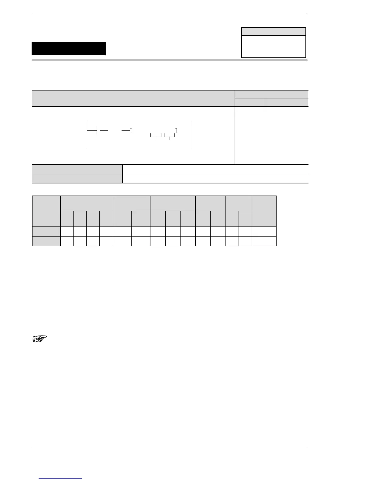
When the ICTL instruction is executed, the interrupt program enable/disable and interrupt clear are set
according to the settings in S1 and S2.
Be sure to use ICTL instructions so that they are executed once at the leading edge of the execution condition
(trigger) using the DF instruction.
Two or more ICTL instructions can have the same execution condition (trigger).
Note
Before executing an interrupt program, be sure to execute the
ICTL instruction and enable the execution of the interrupt
program.
Flag conditions
・Error flag (R9007, R9008):
− It turns on, when the specified address using the index modifier exceeds a
limit.
− It turns on, when the value outside of the range is specified for the
interruption type and control function of [S1].
− It turns on, when the value outside of the range is specified for [S2].
FP2/FP2SH/FP10SH
ICTL
Interrupt control
FP2/FP2SH/FP10SH
Availability
A: Available






 To Next Page