Basic Instructions
2 − 111
Input examples
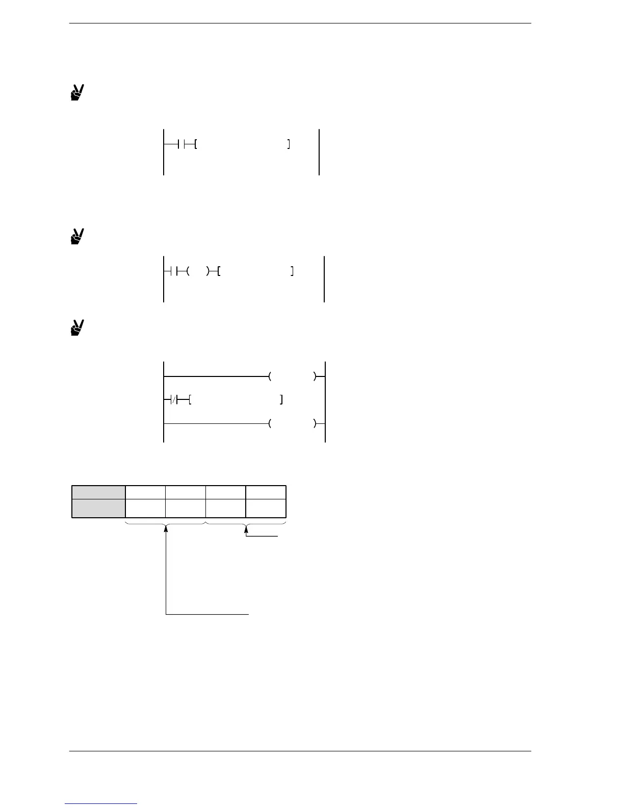
Example 1: Setting a periodical interrupt every 10ms from the start of
operations
ICTL, H2, K1
R9013
Executes INT24 every 10ms
The R9013 (initial pulse relay) turns on only for the first scan
after operations begin.
Example 2: Enable INT0 through INT3 when X30 rises.
ICTL, H0, HF
X30
DF
X30: Enables INT0 to INT3 when on
Example 3: Clear interrupts other than INT0 after the INT0 program is
completed.
INT 0
ICTL, H100, H1
R0
IRET
Interrupts other than INT0 are
cleared when the program of
INT0 is finished
Specifying control data
S1: Specifying the control functions and interrupt types
87 43 012 1115
S1
.. .. .. ..
Bit position
Selection of control function
H00: Interrupt execution “enabled/disabled”
H01: Interrupt clear
Interrupt type selection
H00: INT 0 to INT15
H01: INT16 to INT23 (*1)
H02: INT24 (10ms units)
H03: INT24 (0.5ms units) (*2)
H04: INT24 (in increments of 10 ms) (*3)
H05: INT24 (in increments of 0.5 ms) (*3)
(*1) The intelligent unit which issues interrupts has a high−speed counter unit, a pulse output unit, and other
units.
(*2) FP2/FP2SH/FP10SH only
(*3) Available from FP2/FP2SH Ver. 1.50 or later
FP2/FP2SH/FP10SH






 To Next Page