Basic Instructions
2 − 133
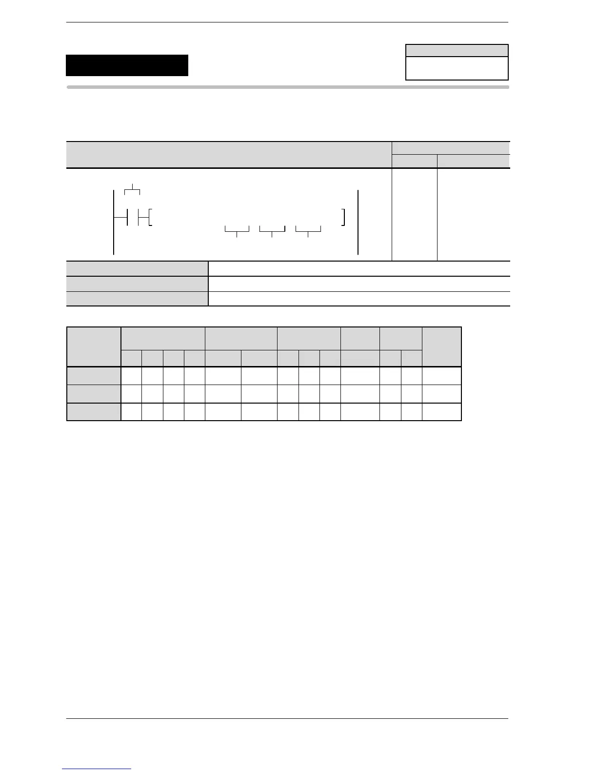
Outline This changes the settings entered for the system registers of the PLC
link function, in accordance with the specified data.
Program example
Boolean
Ladder Diagram
Address Instruction
S
Trigger
D2D1
SYS2,
10
R0
DT0, K40, K47
10
11
ST R 0
SYS2
DT 0
K40
K47
S Starting number of the area in which 16−bit data is stored
D1 Starting number of the system registers being specified (K40 to K47)
D2 Ending number of the system registers being specified (K40 to K47)
Operands
O
WX WY WR WL SV EV DT LD FL I K H
modifier
S N/A N/A N/A N/A N/A N/A A N/A N/A N/A N/A N/A N/A
D1 N/A N/A N/A N/A N/A N/A N/A N/A N/A N/A A N/A N/A
D2 N/A N/A N/A N/A N/A N/A N/A N/A N/A N/A A N/A N/A
Description
The contents of system registers No. 40 to No. 47 are changed to the contents of the data registers starting
with the number specified by [S].
Note) With the FP0R, the FPΣ 32k and the FP−X, the contents of system registers No. 50 to No. 57 are also
changed.
FPΣ/FP−X/FP0R
SYS2
Availability
FPΣ/FP−X/FP0R
Change system registers
(No. 40 to No. 47, No. 50 to No. 57)






 To Next Page