Basic Instructions
2 − 141
Explanation of example
Compares the real number value of data registers (DT0, DT1) with the real number value of data registers
(DT100, DT101). If (DT0, DT1) = (DT100, DT101), the external output relay Y30 goes on and if (DT0, DT1) >
(DT100, DT101), the external output relay Y31 goes on.
Description
Compares the real number data specified by S1 and S1+1 with the real number data specified by S2 and
S2+1 according to the comparison condition.
The STF instruction initiates a logical operation as the liaison contact when the comparison result is a
specified status (=, <, >, etc.).
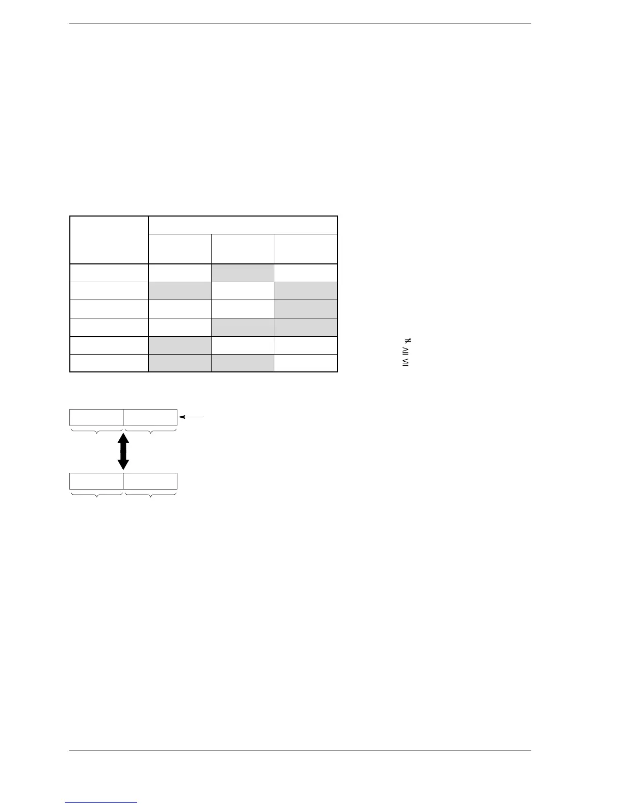
The result of the comparison operation is as follows:
Comparison
Condition
instruction
(S1+1, S1) <
(S2+2, S2)
(S1+1, S1) =
(S2+2, S2)
(S1+1, S1) >
(S2+2, S2)
STF= off on off
STF<> on off on
STF> off off on
STF>= off on on
STF< on off off
STF<= on on off
When processing 32-bit data, the higher 16-bit areas (S1+1, S2+1) are automatically determined once the
lower 16-bit areas (S1, S2) are specified.
S1S1+1
S2S2+1
The specified data area and the following data area are handled
together as single precision real number data.
Comparison
Precautions concerning usage
The start comparison instructions STF =, STF <>, STF >, STF >=, STF <, and STF <= are programmed from
the bus line.
Specifying the integer device with [S1] and [S2], the integer data is internally converted to real numbers
before operations continue.
When the constant K is specified in S1 and S2, the operations are the same as when a integer device is
specified.
Flag conditions
・Error flag (R9007): Turns on and stays on when:
・Error flag (R9008): Turns on for an instant when:
− The area specified using the index modifier exceeds the limit.
− If data other than real number data are specified in (S1+1, S1) and (S2+1,
S2).
< > indicates
>= indicates
<= indicates







 To Next Page