High−level Instructions
3 − 8
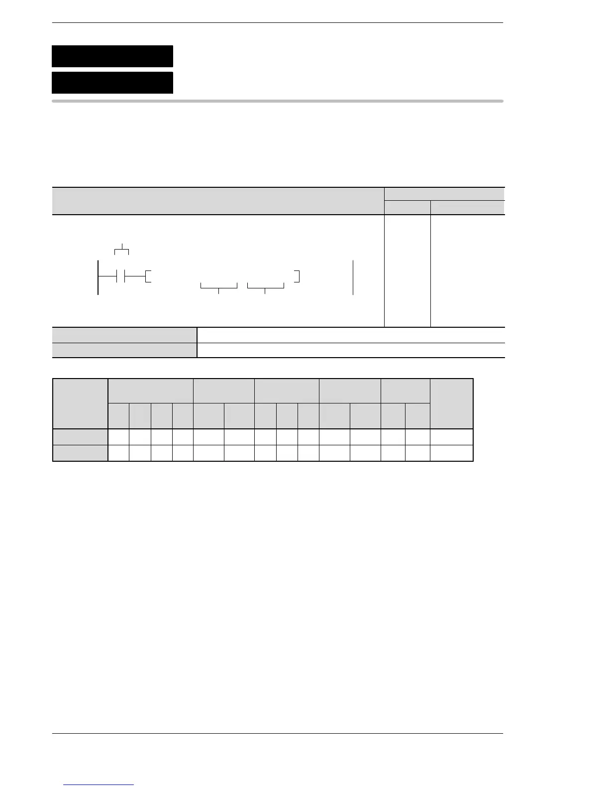
Outline Copies 16-bit data to the specified 16-bit area.
For the FP0R/FPΣ/FP−X/FP0/FP−e, the P type high−level instruction
“P0 (PMV)” is not available.
Program example
modifier
S A A A A A A A A A A A A A A
D N/A A A A A A A A A A A N/A N/A A
(*1) This cannot be used with the FP0 and FP−e.
(*2) This cannot be used with the FP0, FP−e, FP0R, FPΣ, FP−X.
(*3) With the FP0R, FPΣ,FP−X, FP2, FP2SH, and FP10SH, this is I0 to IC.
(*4) With the FP0R, FPΣ,FP−X, FP2, FP2SH, and FP10SH, this is ID.
Explanation of example
The contents of data register DT10 are copied to data register DT20 when trigger R0 turns on.
Description
The 16-bit data or 16-bit equivalent constant specified by S is copied to the area specified by D.
Reference
When using an FP0/FP−e/FP0R/FPΣ/FP−X high −speed counter: F0 (MV) page 3 − 437
When using an FP0/FP−e/FP0R/FPΣ/FP−X pulse output: F0 (MV) page 3 − 443
F0
P0
16-bit data move
(MV)
(PMV)
A: Available
N/A: Not Available






 To Next Page