High−level Instructions
3 − 10
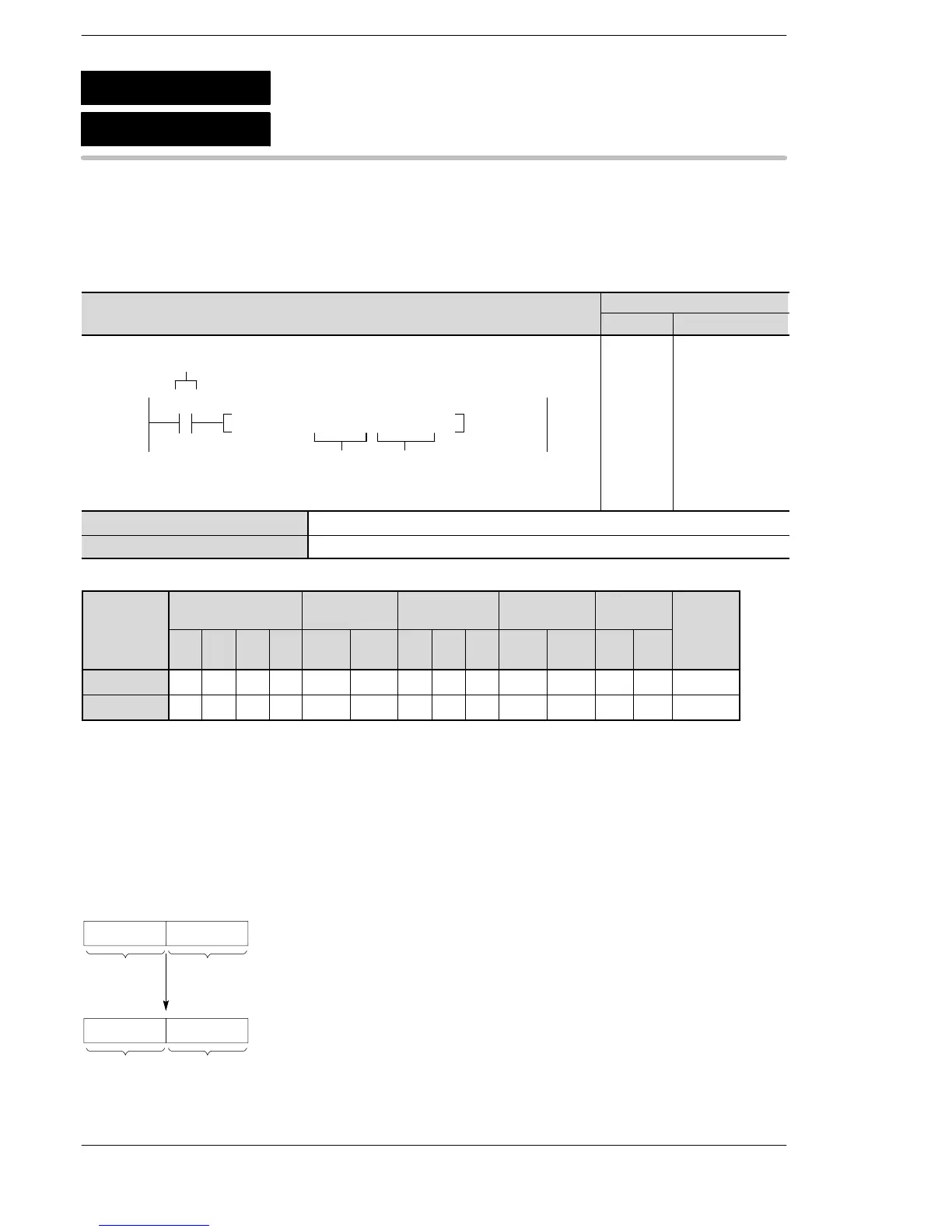
Outline Copies 32-bit data to the specified 32-bit area.
For the FP0R/FPΣ/FP−X/FP0/FP−e, the P type high−level instruction
“P1 (PDMV)” is not available.
Program example
Boolean
Ladder Diagram
Address Instruction
10
F1 DMV , DT 10 , DT20
S
D
Trigger
R0
10
11
ST R 0
F 1 (DMV)
DT 10
DT 20
S 32-bit equivalent constant or lower 16-bit area of 32-bit data (source)
D Lower 16-bit area for 32-bit area (destination)
Operands
modifier
S A A A A A A A A A A N/A A A A
D N/A A A A A A A A A A N/A N/A N/A A
(*1) This cannot be used with the FP0 and FP−e.
(*2) This cannot be used with the FP0, FP−e, FP0R, FPΣ, FP−X.
(*3) With the FP0R, FPΣ,FP−X, FP2, FP2SH, and FP10SH, this is I0 to IC.
(*4) With the FP0R, FPΣ,FP−X, FP2, FP2SH, and FP10SH, this is ID.
Explanation of example
The contents of data registers DT11 and DT10 are copied to data registers DT21 and DT20 when trigger R0
turns on.
Content for
DT11
To DT20To DT21
.... The content (16 bits) of DT10 and the content (16 bits) of DT11 are joined and
treated as 32−bit data.
Higher
16−bit area
Lower
16−bit area
Content for
DT10
.... 32−bit data is separated into the higher 16−bit data and the lower 16−bit data,
and stored in DT21 and DT20.
F1
P1
32-bit data move
(DMV)
(PDMV)
A: Available
N/A: Not Available






 To Next Page