High−level Instructions
3 − 29
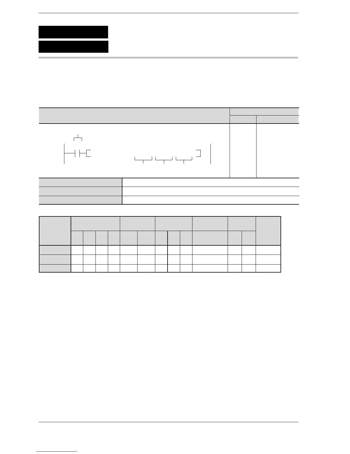
Outline Copies block data to the specified area.
For the FP0R/FPΣ/FP−X/FP0/FP−e, the P type high−level instructions
are not available.
4
Program example
Boolean
Ladder Diagram
Address Instruction
10
F10 BKMV , DT 0 , DT 3 , DT 10
S1
D
Trigger
S2
R0
10
11
ST R 0
F 10 (BKMV)
DT 0
DT 3
DT 10
S1 Starting 16-bit area (source)
S2 Ending 16-bit area (source)
D Starting 16-bit area (destination)
Operands
modifier
S1 A A A A A A A A A N/A N/A N/A A
S2 A A A A A A A A A N/A N/A N/A A
D N/A A A A A A A A A N/A N/A N/A A
(*1) This cannot be used with the FP0 and FP−e.
(*2) This cannot be used with the FP0, FP−e, FP0R, FPΣ, FP−X.
Description
The data block specified by S1 and S2 is copied to the block starting from the 16-bit area specified by D.
Precautions during programming
The starting area S1 and ending area S2 should be the same type of operand.
The number of the lower address should be specified by S1, and the number of the higher address should be
specified by S2. If S1 is specified as higher than S2 and the instruction is executed, an operation error will
occur.
F10
P10
Block move
(BKMV)
(PBKMV)
A: Available
N/A: Not Available






 To Next Page