High−level Instructions
3 − 32
Explanation of example
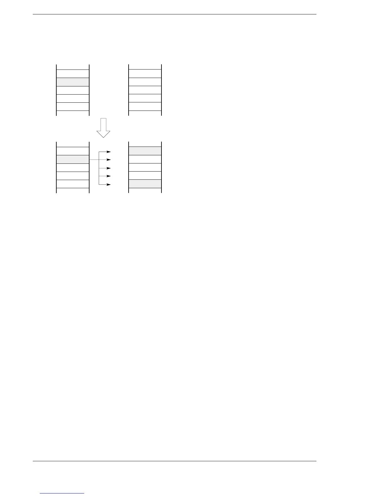
The contents of data register DT0 are copied to the block ranging from data register DT10 to DT14 when
trigger R0 turns on.
K0
K11
K10
K12
DT0
[S] DT1
DT2
DT3
DT4
K0
K0
DT10
DT11
DT12
DT13
DT14
R0: on “F11 (COPY)” execution
K0
K13
K14
K0
K11
K11
K10
K12
DT0
[S] DT1
DT2
DT3
DT4
K11
K11
K11
K13
K14
K11
[D1]
[D2]
[D1]
[D2]
DT10
DT11
DT12
DT13
DT14
Description
The 16-bit equivalent constant or 16-bit area specified by S is copied to all 16-bit areas of the block specified
by D1 and D2.
Precautions during programming
The starting area D1 and ending area D2 should be the same type of operand.
The area of the lower address for the block being copied should be specified by D1, and the higher address
should be specified by D2. If D1 is specified as higher than D2 and the instruction is executed, an operation
error will occur.
When the same number as D1 and D2 is specified, the 16−bit data will be copied to the 16−bit area of that
number.
Flag conditions
・Error flag (R9007): Turns on and stays on when:
・Error flag (R9008): Turns on for an instant when:
− The area specified using the index modifier exceeds the limit.
− D1 > D2.







 To Next Page