High−level Instructions
3 − 132
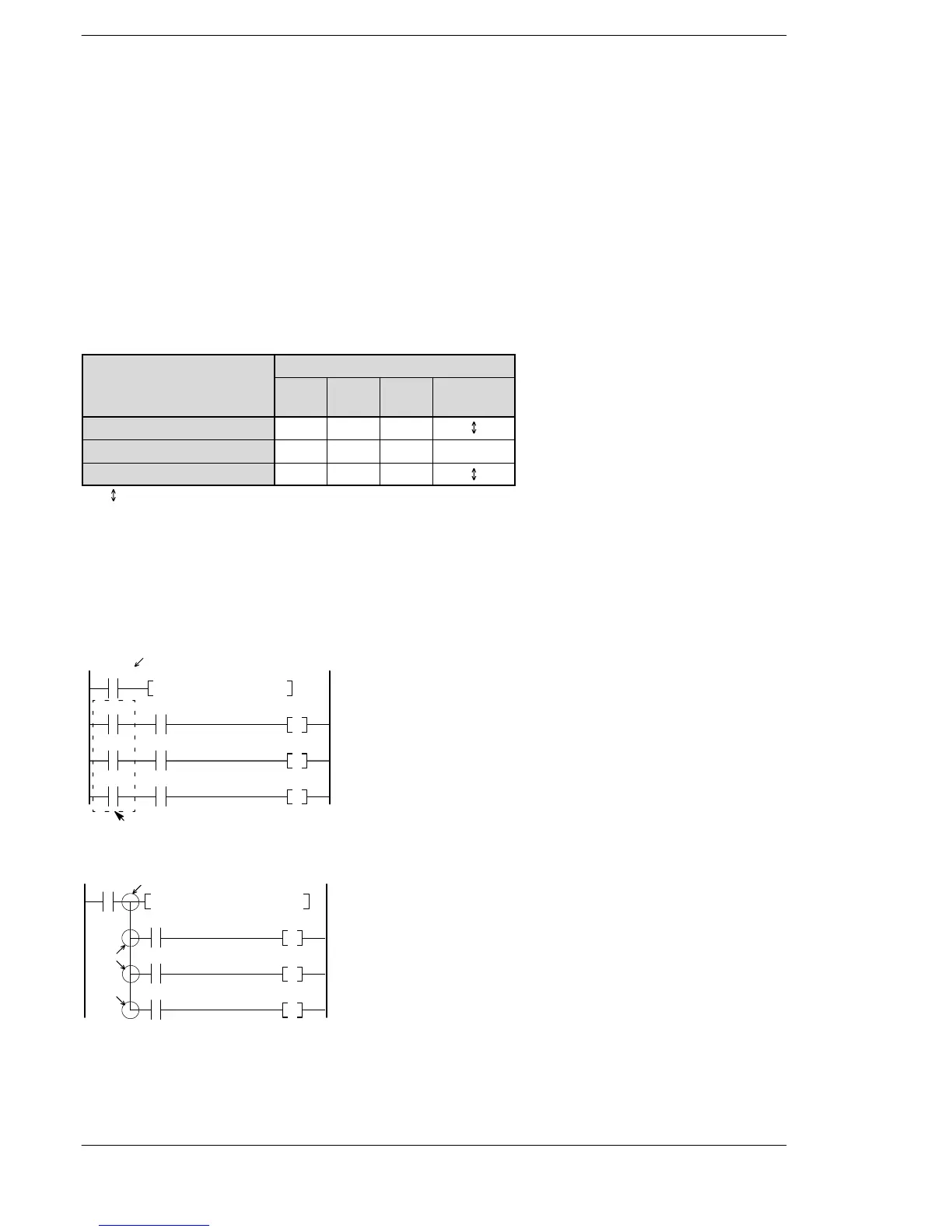
Explanation of example
Compares the content (32−bit data) of data registers DT11 and DT10 with the content (32−bit data) of data
registers DT1 and DT0 when trigger R0 turns on.
When (DT1 and DT0) > (DT11 and DT10), R900A turns on and external output relay Y10 turns on.
When (DT1 and DT0) = (DT11 and DT10), R900B turns on and external output relay Y11 turns on.
When (DT1 and DT0) < (DT11 and DT10), R900C turns on and external output relay Y12 turns on.
Description
Compares the 32-bit data or 32-bit equivalent constant specified by S1 with that specified by S2. The
comparison result is output to special internal relays R9009, R900A, 900B, and R900C.
The following table lists the states of the carry flag (R9009), > flag (R900A), = flag (R900B), and < flag
(R900C), depending on the relative sizes of (S1+1, S1) and (S2+1, S2).
Flag
Comparison between
(S1+1, S1) and (S2+1, S2)
R900A
(> flag)
R900B
(= flag)
R900C
(< flag)
R9009
(carry flag)
(S1+1, S1) < (S2+1, S2)
off off on
(S1+1, S1) = (S2+1, S2)
off on off off
(S1+1, S1) > (S2+1, S2)
on off off
“ ”: turns on or off according to the conditions
When processing 32-bit data, the higher 16-bit areas (S1+1, S2+1) are automatically determined once the
lower 16-bit areas (S1, S2) are specified.
Execution condition (Trigger)
In this program example, the comparison will be performed only when R0 turns on.
If ongoing comparison is necessary, relay R9010, which is always on, should be used in the execution
conditions.
R9010 can be eliminated in this case.
Y10
Y11
Y12
R9010
R9010
R9010
R9010
F61 CMP, DT 0, DT10
R900A
R900B
R900C
Always on relay.
You can also program the above using the PSHS, RDS, and POPS instructions.
RDS
Y10
POPS
Y11
Y12
X0
F61 DCMP, DT 0, DT10
R900A
R900B
R900C
PSHS
This is a program in which operation is the same as the above program.
Phone: 800.894.0412 - Fax: 888.723.4773 - Web: www.clrwtr.com - Email: info@clrwtr.com





 To Next Page