High−level Instructions
3 − 154
Description
Creates Block Check Code (BCC) from the starting position for the calculation specified by “S1” and “S2”
using the calculation method specified by “S1”, and stores the result at the position specified by “D” and “S1”
according to the conversion method specified by “S1”.
H
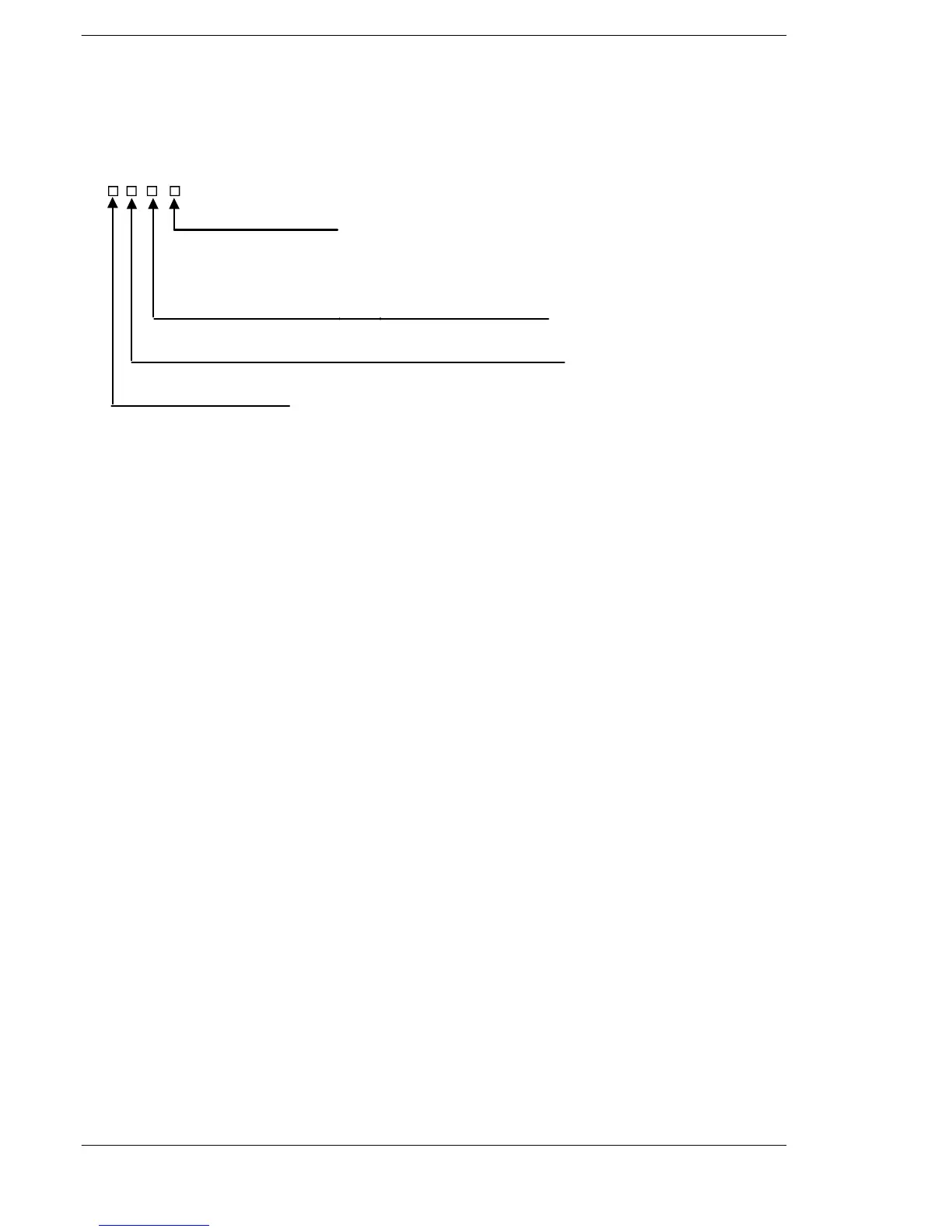
BCC calculation method
Conversion data
0: Binary data (CRC : 2 bytes / Not CRC : 1 bytes)
1: ASCII code (2 bytes)
Starting byte position for storing results (No. of bytes from “D”)
0toF
Starting byte position for calculation (No. of bytes from “S2”)
0toF
0: Addition
1: Subtraction
2: Exclusive OR operation
A: CRC−16
Note 2)
Note 2)
Note 2)
Note 1) If CRC−16 is specified as the calculation method, ASCII code cannot be specified for the conversion
data.
How to specify control data “S1”
Note 2) This can be used with the FP0R, FP−X (V2.00 or more) and FPΣ (V3.10 or more).
How to calculate the Block Check Code (BCC)
If BCC calculation method specified by “S1” is CRC,
The following generation polynomial is used and calculated (The same as MODBUS−RTU).
The generation polynomial : X^15+X^13+1 (H A001)
Flag conditions
Σ Error flag (R9007): Turns on and stays on when:
Σ Error flag (R9008): Turns on for an instant when:
− BCC calculation method specified by “S1” is outside the specification range
− Conversion data specified by “S1” is outside the specification range







 To Next Page