High−level Instructions
3 − 201
Explanation of example
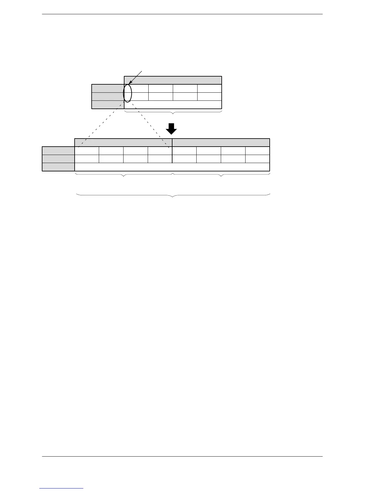
Copies the sign bit of data register DT0 to all the bits of data register DT1 when trigger R20 turns on.
If K−2 is stored in DT0, the data will be as follows.
····
Bit position
·····
Binary data
15 1211 8 7 4 3 0
R20: on
Decimal data
·········
15
1
1211
11
8
1
7
11
4
1
3
10
0
Higher 16-bit area
(extended 16-bit area)
Lower 16-bit area
DT1 DT0
····
Bit position
·····
Binary data
15
1
1211
11
8
1
7
11
4
1
3
10
0
Decimal data
DT0
Sign bit (0: positive, 1: negative)
111 1 1 11
K−2
111 1 1 111 1111111111 1 1 111
K−2
16-bit data
32-bit data
Description
16−bit data is converted to 32−bit data, without signs and values being changed.
If the sign bit (bit position 15) of the 16−bit data specified by D is 0, all 16 bits of the next area of D will be set to
0. If the sign bit is 1, all 16 bits will be set to 1.
By doing this, the 16−bit data is converted to 32−bit data, without the sign or the values changing.
Double word data with D as the first data can be used as the operand of 32−bitoperation instructions following
execution of the F89 (EXT) instruction.
Flag conditions
・Error flag (R9007): Turns on and stays on when the area specified using the index modifier
exceeds the limit.
・Error flag (R9008): Turns on for an instant when the area specified using the index modifier
exceeds the limit.





 To Next Page