High−level Instructions
3 − 261
Explanation of example
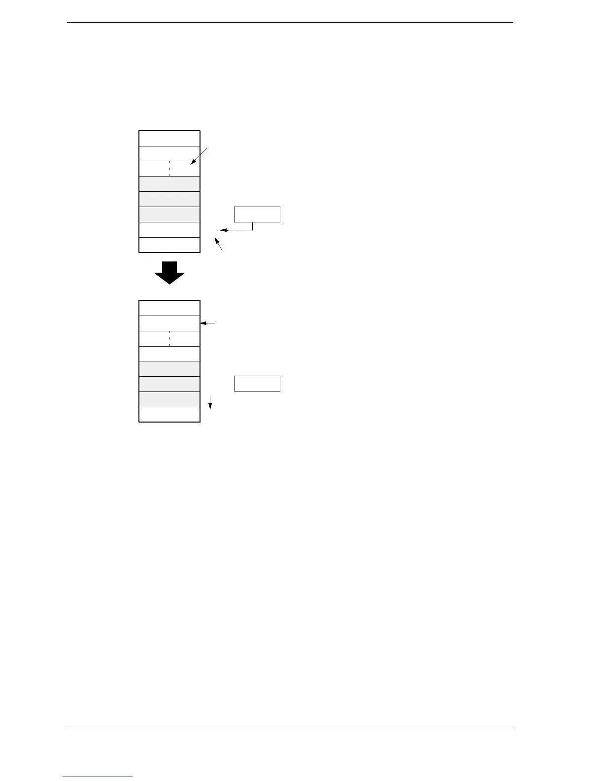
When the execution condition (trigger) R10 is on, the contents of DT110 are written to the FIFO buffer area
headed by DT0.
When the writing pointer is 3
K101
K100
0
DT0
DT1
DT2
15 0
DT3
(H0003)
DT4
DT6
0
1
2
3 ▲
DT7
4
K5
K3
K101
K102
K500
3
Read
pointer▲
DT5
0
DT0
DT1
DT2
15 0
▲DT3
(H0004)
DT4
DT6
0
1
2
3
DT7
4▲
K5
K4
K100
K102
K103
4
DT5
F117 (FIFW) execution
DT110
DT110
K103
Writing
K103
Writing pointer
Number of stored data items
Writing pointer moved
Writing pointer
The contents “103” of DT110 are sent to DT6, which is indicated by the pointer 3.
After the data has been written, 1 is added to the contents of DT1 (the number of stored data items), and the
writing pointer moves to 4.
(The next time that writing is carried out, the contents of DT110 are written to DT7, indicated by the 4.)





 To Next Page