High−level Instructions
3 − 296
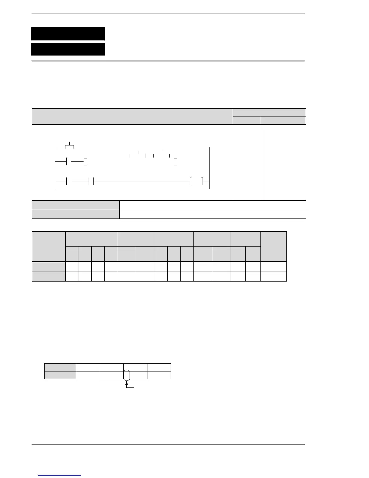
Outline Checks the state [on (1) or off (0)] of the specified bit in 16-bit data.
For the FP0R/FPΣ/FP−X/FP0/FP−e, the P type high−level instruction
“P133 (PBTT)” is not available.
Program example
modifier
D N/A A A A A A A A A A A N/A N/A A
n A A A A A A A A A A A A A A
(*1) This cannot be used with the FP0 and FP−e.
(*2) This cannot be used with the FP0, FP−e, FP0R, FPΣ, FP−X.
(*3) With the FP0R, FPΣ,FP−X, FP2, FP2SH, and FP10SH, this is I0 to IC.
(*4) With the FP0R, FPΣ,FP−X, FP2, FP2SH, and FP10SH, this is ID.
Explanation of example
Checks the state [on (1) or off (0)] of bit specified by DT2 in data register DT0 when trigger R0 turns on. If bit
specified by DT2 is in the off (0) state, internal relay R10 goes on.
When the DT2 = K7, as shown below.
The state of bit position 7 is checked.
····
Bit position
·····
DT0
15
010
12
0
11
001
8
1
7
001
4
0
3
000
0
1
[D]
[n] DT2:K7
If bit position 7 is in the off state (0), R900B turns on and internal relay R10 goes on.
F133
P133
(PBTT)
(BTT)
16-bit data bit test
A: Available
N/A: Not Available





 To Next Page